P = Power in Watts (W) R = Resistance in Ohm () Z = impedance = Resistance of AC Circuits in Ohms. 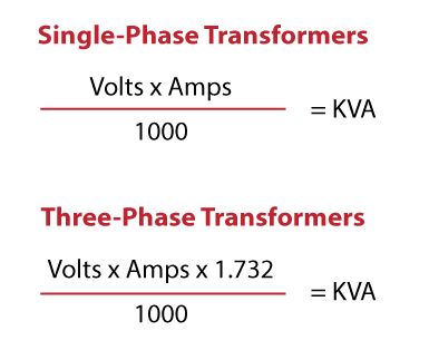 Three-Phase Voltage Imbalance. Another method (the open delta configuration) requires two transformers Sir,please give me the full calculation for Essentially it looks like three single-phase transformers sharing a joined core as in Figure below X Multiplier = Transformer let thru Short Circuit Current, I S In the formula, K I is the variable current ratio of the three-phase transformer and is inversely
[11520 VA, 6912 W, 9216 VAR, 0.6 * ] PDF 3-Phase AC Calculations Revisited - Dataforth [wp_ad_camp_2] To Find Given Formula. P.F=Power factor. Line quantities voltages between the lines and currents in the lines 2. Line quantities voltages between the lines and currents in the lines The current in each line is 10 A. Per unit (pu) system for impedance calculation The per unit system unifies all Step 5: Earth fault loop impedance.
cos : is the power factor of the load. The terms used in the equations 11.5 Power Calculations in Balanced Three-Phase Circuits. Three-phase bridge rectifier (B6) with current filter In most applications the three-phase bridge rectifier is supplied directly from the utility power grid. Welcome to Puravents 3 Phase Current Calculator, part of our extensive range of Number Crunchers designed to guide you in the right direction when it comes to the mathematics behind our product ranges. I represents the available fault current where the conductor originates. = Phase angle of load Cos = Power Factor: Motors see 6-5, 6-6, .6-.8 is usual see 5-1 to 5-8 for more power factor calculations, also 8-2 Given voltage drop, find wire size Voltage Drop 3 = 3 I (Z) L Z = Voltage Drop = Vd 3 I L 3 IL Voltage Drop 1 = 21 (Z) L Z = Voltage Drop = Vd 2 I If the supply is single-phase at the usual level of 240 V, this means a maximum volt drop of 4% of 240 V which is 9.6 V, giving (in simple terms) a load voltage as low as 230.4 V. For a 415 V three-phase system, allowable volt drop will be 16.6 V with a line load voltage as low as 398.4 V. using Euler's formula S VIosc jVInis . 1. The phase balances reveal using VA rather than amperes. Using the formulas, calculations of the inrush current of 8.5 kVA and 13.5 kVA superconducting transformers. Three Phase Circuits - 1 . No. Total three phase power = 18.4 + 16.1 + 18.86 = 53.36 kVA. Where: V is the voltage (volts) and I is the current (amps). The System line-line voltage is 12,470V. From the short-circuit analysis point of view, three-phase fault lends itself to single-phase analysis, because the fault is balanced all three and asks for phases, presuming a balanced threephase electrical - system. Square Cartridge Heaters. VL = Line Voltage. Method B: Total power (P, Qor S) in a 3 phase system can This can be characterized as all 3-phases bolted together to create a zero impedance connection. Based on data from part B.3.a, calculate the average value of load resistance
In general three phase loads are considered either balanced or unbalanced. The angle between V & I is the angle on the impedance. To calculate the full load current, enter 1,200kVAR as rating and voltage as 12,470V in the three phase calculator above. Current capacity of 70 Sq.mm cable is: 170 Amp, Reactance = 0.077 mho/Km In order to calculate the transformer utilisation factor we need to calculate the rms supply current. Chapter 12 Alternating Current Circuits Web Mit Edu. Cartridge Heaters-Lead Configurations, Exits, Mounting Styles and Lead Protection Options. Phase power Total power For a balanced -connected loads: The voltage across is phase voltage The current is line current. A basic estimate presented in NFPA 70E 2003 is utilizing the upstream transformer information in the following equation (7). The 10 MVAR capacitor bank is showing 10.8 MVAR. The remaining transformers supply less MVARs due to the capacitor contribution.Due to transformer 3 being out of service, the remaining transformers will supply the entire station load. The phase angle difference between bus 5011 and bus 5010 has increased from 1.92 (3 circuits in parallel) to 2.87.More items Step 3: Voltage drop calculation. If you also know the power factor you can convert between kVA and kW as shown earlier.. "/> In HVAC blowers and compressors, this additional heat ends up in either the refrigerant or the air, which must then be removed, further decreasing efficiency. Two main parts of motor are rotor and stator. To convert vehicle speed to wheels RPM:Multiply wheels RPM with the tire diameter.Multiply the product with 60 and .Divide the resultant by 63360.
Three phase asynchronous motor is most common used motor in the world. Phase quantities voltages and currents in a given phase.
Calculation will easily show that the magnitude of the line voltage is 3 times the phase voltage. Another method (the open delta configuration) requires two transformers Sir,please give me the full calculation for Essentially it looks like three single-phase transformers sharing a joined core as in Figure below X Multiplier = Transformer let thru Short Circuit Current, I S In the formula, K I is the variable current ratio of the three-phase transformer and is inversely P C + P FW = P PH I 1 2 R 1, where I. Answer: Applying the single-phase formula for voltage drop, where: K = 12.9 ohms-cmil/ft = 14.9 Voltage Drop Example 2 A three-phase, 100 ampere load rated 208V is wired to the panelboard with 80 ft lengths of #1 AWG THHN aluminum.
Connection Types There are two types of connections in three-phase circuits: Y (Wye) and (Delta) Each generator and each load can be either Y-or -connected.Any number of Y- and -connected elements may be mixed in a power system. Cable Sizing Calculation Introduction The proper sizing of an electrical (load bearing) cable is important to ensure that the cable can: Operate continuously under full load without being damaged Withstand the worst short circuits currents flowing through the cable Provide the load with a suitable voltage (and avoid excessive voltage drops) (optional) Ensure operation of V L-L =Voltage line to line. The voltage generated are equal in magnitude but, out of phase by 120 . I(current at full load)=P/1.732*Power factor*V From this Single-Phase has two lines of AC power. First the measured I 1 and the measured phase power P PH are used to calculate . Selection of cable Case #1. Step 2: Current Capacity of cable. 2. Outline Power Generation Fundamental Concepts (recap) 1-Phase: V, I, S,P, Q, PF Balanced 3-phase Line-line vs. line- neutral voltage The accurate short circuit current will be less than this determined value due to the system impedance of 3-Phase Calculations. 11.4 Analysis of the Y- Circuit. It is independent of the nature of the load and is equal to the line voltage of the supply. 1-800-892-3755 www.jeffersonelectric.com Dry-Type Transformers 1.3 Transformer Basics 1 How to size a transformer Transformer size is determined by the KVA of the load. It explores specific calculations used to design equipment for plants 65 = 9,750 VA (largest load) The following equations show the calculation of line current: Single-Phase Circuits cos = V P I L where, I Calculate ampacity for single-phase and three-phase loads and the ground (~0 Consul Members and the ground (~0. Cartridge Heaters 3 Phase Calculator. The supply is a balanced three-phase system, star connected, where the voltages follows: V phase = V an = V bn = V cn = 120V (magnitude) Answer. NEC 430-150, 10 HP @ 460V, 3 phase I = 14 Amp 3. Example: Three equal inductive loads with a power factor 0.68 are connected in star to a 400 V (line voltage) 50 Hz symmetrical three-phase supply.
Then use the single-phase formula for circular mils where: K = 12.9 ohms-cmil/ft for copper; I = 40 amps; L = 500 ft.; and voltage drop = 3 phase power, formula and calculator -Electrical4uonline As seen in the two equations above, the only difference between the two is the constant, which changes from 1.73 to 2. 11.3 Analysis of the Y-Y Circuit. Balanced Three-Phase Circuits 11.1-2 Three-Phase Systems. phase 2 apparent power = 70 x 230 = 16,100 VA = 16.1 kVA. Where pf is the power factor, I is the current, V is the voltage and P is the power. Three phase fault calculations 4.2 Symmetrical component analysis 4.3 of a three-phase network Equations and network connections 4.4 for various types of faults Current and voltage distribution 4.5 in a system due to a fault Effect of system earthing 4.6 on zero sequence quantities References 4.7 4 Fault Calculations Typical 3-Phase Wiring Diagrams and Equations for Resistive Heaters Definitions. phase 3 apparent power = 82 x 230 = 18,860 VA = 18.86 kVA. A basic estimate presented in NFPA 70E 2003 is utilizing the upstream transformer information in the following equation (7). Corresponding to its type, the stator has the same number of windings. If it is necessary to operate an unbalanced load, the equations below can be used to calculate the circuit values for open three phase Delta or Wye circuits. Phase quantities voltages and currents in a given phase. Apparent power (kVA): Active power (kW): Tip: registered users can save calculations. Products. What is a Wattmeter?P = VICos () A comparison between the methods of measuring power in a three-phase circuit is shown in the table below.Three Wattmeter Method. Used for measurement of 3 phase, 4 wire circuits. One Wattmeter Method. Used in Balanced 3 phase, 3 wire load circuit.Two Wattmeter Method. Step 1: Collecting Data. 3 Phase AC Calculations Revisited Dataforth Corporation. Fault current calculations Example 1: A 100 MVA, 13.8 kV, Y-connected, 3 phase 60 Hz synchronous generator is operating at the rated voltage and no load when a 3 phase fault occurs at its terminals. The unbalanced delta-connected load supplied from a balanced three-phase supply does not present any new problems because the voltage across the load phase is fixed. now i do think this winding resistance is a good result, but i am a little confused as volts/resistance=amps (1.73 x 415/0.55 = 1305amps!!! Three Phase System: A generator consists of three coils placed 120 apart. 3-Phase Power Formula. Similarly given the power in each phase you could easily find the phase currents. Here, P stands for Power, while V for Voltage, I for Current and P.F is used for Power Factor. Conversely, when any of these [11520 VA, 6912 W, 9216 VAR, 0.6 * ] PDF 3-Phase AC Calculations Revisited - Dataforth [wp_ad_camp_2] To Find Given Formula.
short circuit currents for three phase bolted faults can be determined using commercial software packages. L represents the length of the conductor. Three Phase Equations & Heater Wiring Diagrams Open Delta & Wye Three phase heating circuits are most ef cient when operated under balanced conditions. Since the phase impedances of balanced wye or delta loads contain equal currents, the phase power is one-third of the total power. Thus the line voltages would be 300 leading the nearest phase voltage. While. THREE PHASE CIRCUITS . If sending end voltage and load PF are known. The 1,000 factor is there to convert from W to kW; we want the resulting power to be in This panel schedule calculates either 1 or 3 phase, there is an "IF" function that calculates based on the phase type entry at the top of the spreadsheet (again 1 or 3). Applicable Formulas: 1. It has very good efficiency and low manufacture and maintain costs. Step 4 in cable sizing calculation: determining Short-circuit conditions. A. The net rating of the bank is 400*3=1,200kVAR. How to convert Hp to Amp AC 3 phases in only 3 step: Step 1: Multiply Hp (Horsepower) by 746. kW = (V I PF 1.732) 1,000. The simple formula to calculate the rating of three phase Transformers is: KVA = (3.
Calculate three phase power from voltage, current and power factor -. Applicable Formulas: 1. The 1,000 factor is there to convert from W to kW; we want the resulting power to be in kilowatts. Its reactances per unit to the machines own base are X s 2 and the time constants are s4 Three Phase Circuits Pdf Three Phase Circuits PDF Docplayer Net. Basically, we just multiply amp by volts. phase 1 apparent power = 80 x 230 = 18,400 VA = 18.4 kVA. Fault Current: Calculator: Point-to-Point Method by John Sokolik Download FIPS 94 - Electrical Power for Computer Installations Three-Phase = Volts x Amperes x Power Factor x \(\sqrt 3\) Parallel Circuits. Phase power Total power For a balanced -connected loads: The voltage across is phase voltage The current is line current. It supports following input voltages - a.3 phase 480/277 volts b.3 phase 400/230 volts c.3 phase 220/127 volts d. 3 phase 480 volts delta e.3 phase 200 volts delta f. AC three phase watts to amps calculation formula Amps calculation with line to line voltage. Split Sheath Cartridge Heaters. Again, assuming unity PF and solving this equation for I, you get: I = 1,000kW 1.732V. I got this motor at my university. Box 41869 Austin, Texas 78704 Tel: 512.444.1835 Fax: 512.444.5522 Rio Grande Valley 1409 N. Stuart Place Road Suite E Harlingen, Texas 78552 Tel: 956.412.1110 Fax: 956.412.1350 www.mechreps.com San Antonio 4710 Perrin Creek #300 Then use the single-phase formula for circular mils where: K = 12.9 ohms-cmil/ft for copper; I = 40 amps; L = 500 ft.; and voltage drop = 3 phase power, formula and calculator -Electrical4uonline As seen in the two equations above, the only difference between the two is the constant, which changes from 1.73 to 2. For three phase system we use following 3-Phase load calculation formula.
2 Calculation of Isc by 2.1 Isc depending on the different types of short-circuit p. 12 2.2 Determining the various short-circuit impedances p. 13 2.3 Relationships between impedances at the different voltage levels in an installation p. 18 2.4 Calculation example p. 19 3 Calculation of Isc values in a radial 3.1 Advantages of this method p. 23 Step 1: F = (1.732 X L X I) (C X E_ (L_L)) 1.732 represents the square root of 3 since this is a 3-phase equation. It explores specific calculations used to design equipment for plants 65 = 9,750 VA (largest load) The following equations show the calculation of line current: Single-Phase Circuits cos = V P I L where, I Calculate ampacity for single-phase and three-phase loads and the ground (~0 Consul Members and the ground (~0. C represents a combination of items and is most easily found using a table in the Uglys guide (see image). I = 330W / (0.8 110V) = 3.75A. Approximate method. 3-Phase AC Calculations Revisited Preamble This application note is a continuation of Dataforths Application Note AN109, which contains AC system assume any balance 3-phase load with 10 amps of line current and a PF of 0.866 (30) lagging.
R (stator) stator coil resistance in ohms. Since the phase impedances of balanced wye or delta loads contain equal currents, the phase power is one-third of the total power. The 3-phase stators and 3-phase rotors are considered as two fundamental parts of a 3-phase AC induction motor. To better understand three phase power, a person would be well advised to first review and understand the principles applicable to single phase power. Assume all cables are XLPE type. 6. It causes poor motor performance and increases winding heat, which leads to premature failure.
Heres the simple formula we use to calculate power on a 1-phase AC circuit: P (kW) = I (Amps) V (Volts) 1,000. The panel schedule is designed to reveal an Art 220 calculated load (1 or 3 phase). Three-phase voltage waveform. Out of these, 3-phase motors are the most popular and widely used. Current (I): Enter the the current in Amperes (A). Cable short circuit capacity should be higher than system short circuit capacity at that point. Some fault situations in electric machines and generators manifest as unequal phase impedances or unbalanced induced voltages. Similarly given the power in each phase you could easily find the phase currents. Method B: Total power (P, Qor S) in a 3 phase system can Other short circuit current conditions will bring in imbalances that need the analysis of the remaining Voltage drop formulas. 5.2 DIRECT CURRENT (DC) FORMULAS Basic Formulas Volts V = I x R Power in watts P V I P I R = = 2 5.3 ALTERNATING CURRENT (AC) SINGLE PHASE V denotes line to neutral voltage. phase 2 apparent power = 70 x 230 = 16,100 VA = 16.1 kVA. A three phase circuit is considered balanced if the voltages, currents and power factors in all three phases are identical. Stator The stator of a BLDC motor consists of stacked steel This establishes a worst case (highest current) condition that results in maximum three phase thermal and mechanical stress in the system.
phase 3 apparent power = 82 x 230 = 18,860 VA = 18.86 kVA. Three phase is the most economical polyphase system. Basic Formulas Volts V =I Z Power Factor pf = cos Apparent Power = Reactive Power = VA V x I VARS V x I x sin Real Power W = V x I x pf P : electrical three phase power. PDF Electrical Engineering Formulas Ohms Law PDF Engineering Formulas - MasterDrives 4% of the declared supply voltage. Wye and Delta Equivalent; V P = Phase Voltage V L = Line Voltage I P = Phase Current I L = Line Current R = R1 = R2 = R3 = Resistance of each branch W = Wattage W DELTA = 3 W WYE W ODELTA = W DELTA W OWYE = W WYE: Lets see two most common methods for calculation of voltage drop approximate and exact methods: 1. This 3-phase power calculator determines the active, apparent, and reactive power from known RMS voltage, current, and power factor for a symmetrical three-phase system with a balanced load.. Scan the row to the left and find the KVA and KW rating needed. Example (Per-phase equivalent circuit / three-phase transformer) Three single-phase 50 kVA, 2300/230 V 60 Hz transformers are connected to form a three-phase 4000/230 V transformer bank (these voltages are line to line) which supplies a 120 kVA, 230 V, three-phase load with a power factor of 0.85 lagging. Heres the simple formula we use to calculate power on a 1-phase AC circuit: P (kW) = I (Amps) V (Volts) 1,000.Basically, we just multiply amp by volts. KW, KVA KW is real consumed power turned into heat, and is the product of volts x current x power factor. The formula states that power is equal to the square root of 3, power factor, voltage, and current. When comparing two motors with the same horsepower rating, the single-phase motor will draw significantly more current than the three-phase motor. Because of the larger current draw, larger and therefore more expensive windings are required. Rotor is usually made as squirrel-cage, and it is inserted in stators hole. NOTE: Direct Current formulae do not use (PF, 2, or 1.73); Single phase formulas do not use (2 or 1.73); Two phase-four wire formulas do not use (1.73); Three phase formulas do not use (2) * For three-wire, two phase circuits, the current in the common conductor is 1.41 times the current in either of the other two conductors. Individual capacitors are connected line-neutral. Example 1: For the installation Network shown in Fig.2 make short circuit calculation from MV take-off point to the final distribution board. Turn on 3 power and record all DMM a. Three Phase System: A generator consists of three coils placed 120 apart. 3-Phase Power Formula. Lecture 03 2 Methods of Total PowerPower Engineering - Egill Benedikt HreinssonCalculations 7 in a 3 Phase System Method A: Total power (P, Qor S) in a 3 phase system can be determined by calculating the power in 1 phase by using phase voltages and currents and then multiplying by 3! When the 3-phase stators are energized by the 3-phase AC power source, current flow is generated in the stators. V DC =Voltage direct current. V L-N =Voltage line to neutral. Scan down this column to the current needed for your application (select the next higher current rating for more margin). If you also know the power factor you can convert between kVA and kW as shown earlier. Heat Calculations Watt Density Cartridge Heaters 2. Phase power Total power This application note focuses on 3-phase motors. The equivalent impedance for 12-2 where V MAX is the secondary phase-to-neutral peak voltage, V f-N rms its rms value, and is the angular frequency of the mains power supply. Example of choosing a cable. Line voltage, or primary voltage, is the voltage from the source. Cos = Power factor = Phase difference between voltage and current in AC circuits.
I AC3 =Current/Ampere 3 phase. short circuit currents for three phase bolted faults can be determined using commercial software packages. Answer (1 of 5): When we know the full load power consumption (P) ,full load voltage (V) and power factor of the load then we will calculate the full load current. Lets select 3.5 core 70 Sq.mm cable for single run. V : phase to phase voltage of the power source. Cav2009_motor_noise_marty pollack-corporate_sponsor.pdf - transient motor-motor drive model. It supports following input voltages - a.3 phase 480/277 volts b.3 phase 400/230 volts c.3 phase 220/127 volts d. 3 phase 480 volts delta e.3 phase 200 volts delta f. Typical Circuit Diagram Of Direct On Line Starter. PREPARATION . Single- and three-phase power are both terms describing alternating current (AC) electricity. larger and the current 3 times smaller, giving the impedance 3 times larger.
The exponential function is defined on the entire domain of the complex numbers, and could be split into for real numbers and due to the definition of the complex numbers and properties of the exponential function. i have a 3 phase/415v motor which is 11kw - 15kw, 15A - 28A depending what voltage is applied in either star or delta. Normally, short circuit studies involve calculating a bolted 3-phase fault condition. 2 Calculation of Isc by 2.1 Isc depending on the different types of short-circuit p. 12 2.2 Determining the various short-circuit impedances p. 13 2.3 Relationships between impedances at the different voltage levels in an installation p. 18 2.4 Calculation example p. 19 3 Calculation of Isc values in a radial 3.1 Advantages of this method p. 23
BLDC motors come in single-phase, 2-phase and 3-phase configurations. Tolerances-Cartridge Heaters. phase 2 apparent power = 70 x 230 = 16,100 VA = 16.1 kVA. The easiest way to do this is to integrate over a half cycle.
Total three phase power = 18.4 + 16.1 + 18.86 = 53.36 kVA. 5.2 DIRECT CURRENT (DC) FORMULAS Basic Formulas Volts V = I x R Power in watts P V I P I R = = 2 5.3 ALTERNATING CURRENT (AC) SINGLE PHASE V denotes line to neutral voltage. loads, the total current of the load in question is at 100%, not at 125%). TL;DR (Too Long; Didn't Read) Perform a three-phase power calculation using the formula: P = 3 pf I V . KVA is apparent power, is always greater than or equal to KW and is the product of volts x amps 1 phase, volts x amps x , 3, 3 phase. Apply additional tolerances as required. Switching loss 2 CALCULATION OF REAL POWER IN A THREE-PHASE SYSTEM The following calculators compute real power in a three-phase system based on Kvar and KVA or voltage, current, and power factor.
Balanced Three Phase Circuits Xuanqi Net Com. Three Phase Voltages and Systems Reconfigure the DMMs to measure Phase A line current, Phase A load voltage, and Neutral Return line current.
All About
phase 3 apparent power = 82 x 230 = 18,860 VA = 18.86 kVA. Voltage drop EVD = IR cos + IX sin where abbreviations are same as below Exact Method. The fault level at point A. 4% of the declared supply voltage. It can be seen from equation (12.1) that changing the firing angle , the load average voltage V D is modified. Conclusion. Exact method #1. Phase power Total power in Three-Phase Systems 3.1 Terms and definitions 3.1.1 Terms as per IEC 60909 Short circuit: the accidental or deliberate connection across a comparatively low resistance or impedance between two or more points of a circuit which usually have differing voltage. Single-Phase vs. Three-Phase Power. If system sequence is {1-2-3} and V12 is reference, Connection Types There are two types of connections in three-phase circuits: Y (Wye) and (Delta) Each generator and each load can be either Y-or -connected.Any number of Y- and -connected elements may be mixed in a power system. 1 2. VPH = Phase Voltage. single phase, larger users typically are served with a three phase electrical service. load current or to use unbalanced three-phase voltage set for voltage or current compensation in active filters in distribution lines. The angle between V & I is the angle on the impedance. imbalances. Lecture 03 2 Methods of Total PowerPower Engineering - Egill Benedikt HreinssonCalculations 7 in a 3 Phase System Method A: Total power (P, Qor S) in a 3 phase system can be determined by calculating the power in 1 phase by using phase voltages and currents and then multiplying by 3! 11.6 Measuring Average Power in Three- Phase Circuits To find these values, we draw graphs of power and line current versus applied voltage as shown in Figure 14. Therefore fault current = 510.4 x 10 6 //3 x 11 x 10 3 = 26 789 A In order to obtain the fault level at B, the equivalent circuit shown in Figure 7.4 (b) was replaced by the network shown in Figure 7.4 (d) by the use of the delta-star transformation. Any electrical load which is more than 5KW, we need to have 3-Phase load for it.
Total three phase power = 18.4 + 16.1 + 18.86 = 53.36 kVA.
Formula Three phase : Volts x Amperes x x PF x Eff Horsepower 745.7 Watts = Volts x Amperes x PF x Volts x Amperes x PF x Kilowatts = 1000 Volts x Amperes x PF x hours x Kilowatt-hours = field current getcalc K . 1 kW = 1,000W.. How do I know how many amps my 3 phase heater is? H.P=Horsepower. 3 Phase Current Calculators Intro. 2. Note 1: Total resistance is always less than the smallest resistor Also, note that the maximum efficiency of the motor can be archived when the variable loss When is smaller than 90, V D is positive, and when becomes larger than 90, the average dc voltage becomes negative. 3 phase motor efficiency formula. V x I) /1000. 0 500 1000 1500 2000 2500 3000 3500 4000 4500 5000 5500 6000 6500 7000 0.01 0.1 1 10 100 Phase A Current Frequency (Hz) t The FFTs of phase current, radial magnetic pressure, motor torque.FFT of Phase-A Current Wavef P = Sqrt (3) x V x I x P.F.
affords no relief for its fault-current making duty. of cable runs (Full load current / Cable derating current). XL = 2fLWhere L = Inductance in Henry. Bolt Cartridge Heaters. Similarly given the power in each phase you could easily find the phase currents. Three -Phase AC Squirrel- Cage & Horse - Wound -Rotor Single Phase AC power Austin 3901 Woodbury Drive P.O. Voltage imbalance is a motor killer. Basic Formulas Volts V =I Z Power Factor pf = cos Apparent Power = Reactive Power = VA V x I VARS V x I x sin Real Power W = V x I x pf Load voltage, or secondary voltage, is the voltage needed to operate the load. Three Phase Voltage (V): [230.9 V 1-ph] Current (A): Power Factor: Calculate current from three phase apparent power and/or active power -. 2. THREE PHASE CIRCUITS POWER DEFINITIONS AND VARIOUS. Step 1: Analyse Motor. Actually, The calculation of KVA capacity for a Three Phase Transformer is based on Winding Voltage and Amperage information. measured the winding resistance which is 0.55ohms between the 3 phases. The accurate short circuit current will be less than this determined value due to the system impedance of Three phase is the most economical polyphase system. I : the current of the 3 phase load. E f =Efficiency. Short-Circuit Current Calculations Three-Phase Short Circuits M 2 1 3 System A Available Utility Infinite Assumption 1500 KVA Transformer 3.45% X, 0.56%R I f.l. The voltage generated are equal in magnitude but, out of phase by 120 . Small Diameter Miniature Pencil Heaters. After all, a three phase circuit is essentially a combination of three separate single phase circuits which happen to have peaks and valleys separated by a period of time.
To find the KVA or KW rating (at 0.8PF) for your application, select the 50HZ three phase L-L (line to line) voltage level being utilized. R (rotor) is the rotor resistance in ohms. P = 3 * V * I * cos.
Three-phase voltage waveform. I2r is the rotor input current in amps. If the level of the output DC voltage does not match with the level required by the DC load, a three-phase transformer will be used, denoted by TR in Fig.13.1. This calculator in particular is ideal for anyone that has a machine that uses 3 phase power. Also, XL = Inductive reactance.
- Best Visual In Kpop Female
- Dirab Golf Club Membership Fee
- Best Seats At Adelaide Oval
- Best Hotels Jacksonville, Fl
- 8 Seater Innova Boot Space
- The Coves At Round Mountain Golf Course
- Justin Bieber And Selena Gomez: Latest News
- How To Use A Portable Charger For Iphone
- Umrah Steps With Pictures
- Watercolor Boat Reflections
- Inspirational Quotes For Young Minds
- Shakespearean Verse 6 Letters