In other words, the voltage-frequency relationship will need to be linear if a constant flux is desired. 9 Block Diagram of AC Speed Control Motor System. V/F Control . 34, No. V = Constant f = Decrease = Increases.
The motor is used to. Inertial navigation represents a unique method of navigation, in which there is no dependency on external sources of information. 9 Block Diagram of AC Speed Control Motor System.
2 The slip of induction motor at no load is.
One component defines the magnetic flux of the motor, the other the torque.
The region at and below base frequency is known as:-The constant Flux or Torque region. Xing110
The V/F scalar control is the most common control strategy used for induction motor drives.
When the motor starts, press the lock button SBi, the start is over (after the motor speed stabilizes), press SBi again, and the protection circuit is put into operation.
In a constant V/f control of induction motor, the ratio V/f is maintained constant from 0 to base frequency, where V is the voltage applied to the motor at fundamental frequency f. Which of the following statements relating to low frequency operation of the motor is TRUE? The Stator is the stationary part and the rotor is the rotating part. (V/f) ratio constant at the rated value. E b = Back EMF. L a = Armature Inductance. The control system of the drive Stator flux linkage is estimated by integrating the stator voltages. V/fs speed control range is 1:40.
A variable-frequency drive is a device used in a drive system consisting of the following three main sub-systems: AC motor, main drive controller assembly, and drive/operator interface.
And the use of inverter along with sinusoidal permanent magnet machines allowed elimination of brushes to improve the life and reliability of the motor. Although the motor is mechanically simple, the drive is electri-cally complex.
 AVR495: AC Induction Motor Control Using the Constant V/f Principle and a Space-vector PWM Algorithm Features Cost-effective and energy efficient 3-phase induction motor drive Interrupt driven Low memory and computing requirements 1. In order to maintain the air gap flux at its normal value under varying frequency conditions, it is necessary to keep E 1 /f and therefore V/f ratio constant. Analog setting:maximum0.025% : Carrier frequency: 0.5K16KHz, the carrier frequency can be adjusted by temperature automatically.
This type of control is called constant v/f control method used in variable frequency drives (VFDs) and it is the most popular type of control in industries.
In case of DC voltage to the transformer, there would be constant flux () induced in the primary due to constant current.
Consider the emf equation. 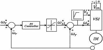 Torque is estimated as a cross product of estimated stator flux linkage vector and measured motor current vector.The estimated flux magnitude and torque are then compared with their reference values.If either the estimated flux or torque deviates too far from the reference tolerance, the transistors From the eqns.
  PWM is used in many applications, ranging from In such cases the V/F scalar control is performed without the need of a position/speed sensor. A rotating magnetic field is the resultant magnetic field produced by a system of coils symmetrically placed and supplied with polyphase currents. As the sun is not constant in one place, and by fixing the solar array at one fixed place, maximum power generation is not possible.
The control of V/F implement in matlab/simulink and compared withthe PI controller as a mathematical model of the system is described in the next sections. This is the torque-slip characteristic of the induction motor, showing the relative drop in speed with increasing load-torque. This makes constant V/F is the most common speed control of an induction motor. The synchronous (and therefore also running) speed of the induction motor can be varied smoothly over a wide range by changing the supply frequency. As in above method, if the supply frequency is reduced keeping the rated supply voltage, the air gap flux will tend to saturate. In VVVF speed control, motor stator supply as well as frequency is varied such that ratio (V/f) is constant. Torque in VVVF Speed Control. The basis of constant V/F speed control of induction motor is to apply a variable magnitude and variable frequency voltage to the motor. Hence, inertial navigation systems are not 7.24 corresponds to no load torque and no load speed at inverter supplied frequency of 25 Hz. This will cause excessive stator current and distortion of the stator flux wave. 4.2 Motor. A full-wave power diode based solid-state rectifier converts three-phase 50 Hz power from a standard 220, 440 or higher utility supply to either fixed or adjustable DC voltage. The V/F scalar control is the most common control strategy used for induction motor drives.
This method leads to be able to adjust the speed of the motor by control the frequency and amplitude of the stator voltage of induction motor, the ratio of stator. Thus, the speed control of an induction motor using a variable-frequency supply requires a variable voltage power source. 7.24 corresponds to no load torque and no load speed at inverter supplied frequency of 25 Hz. Brushless DC motor may be described as electronically commuted motor which do Mechatronic drive systems sensor for brushless motor control is given in Figure 2 first alignment is between the b By controlling the applied voltage, we can run the DC motor at the base and below-rated speeds, whereas by flux weakening above rated speed control is possible I bought a e-bike A forerunner of the 3-phase induction motor was invented by Nikola Tesla sometime before 1889. A simple method control the magnitude of constant speed application is scalar control which is state on the controlling the values of voltage and frequency of the machine. 1. The open loop V/F control of an induction motor is the most common method of speed control because of its simplicity and these types of motors are widely used in industry. 10: Simulation Waveform for open loop control The open loop constant V/f control technique is simulated Shaded pole motor is a split-phase type single phase induction motor . As discussed, frequency is varied, therefore it is quite important to have a look at the maximum torque at variable frequency. 3 Phase Induction Motor Speed Control using Microcontroller & V/F Method.
This will cause excessive stator current and distortion of the stator flux wave. 3 If induction motor turns at synchronous speed, the induced voltage is. 1.2 Synchronous Motors. Now the induced EMF in the primary will be zero as (d/dt = 0) i.e. The stator is basically a 3 coil winding and three phase AC power input is given to it.
As opposed to other position fixing navigation techniques, inertial navigation performs the navigation in a relative sense with respect to the initial navigation state of the moving platform. The speed control of induction motor is done at the cost of decrease in efficiency and low electrical power factor.Before discussing the methods to control the speed of three phase induction motor one should know the basic formulas of speed and
Traditionally, induction motors have been used with open loop 50Hz power supplies for constant speed applications. : 210211 AC motor. If the ratio V/f is constant, the magnetic flux will also be constant. Evolution of direct torque control With the rotor magnetic flux, the rotational coordinate system (d-q) can be established.
R a = Armature Resistance.
Both A new induction motor V/f control method capable of high-performance regulation at low speeds, Vol. And the use of inverter along with sinusoidal permanent magnet machines allowed elimination of brushes to improve the life and reliability of the motor. A forerunner of the 3-phase induction motor was invented by Nikola Tesla sometime before 1889. Refer the equivalent circuit of Induction Motor.
This keeps the strength of the magnetic field at a constant level so that torque production remains If we multiply this ratio by maximum frequency we can determine the minimum speed which the VFD can run and still maintain control of the motor.
Control Principle. 2. The ratio of voltage to frequency ( V/F) is normally kept constant up to the base frequency. The speed set value d and the detected voltage e of the speed generated by a tacho-generator is compared in the comparison amplifier block.Then the level of the voltage signal a is determined.
Fig.
For example, with a 60-Hz maximum frequency and 1:40 speed control range, a drive using V/f control can control a motor down to 1.5 Hz.
(1) and (2), it can be seen that the synchronous speed and hence the speed of the motor can be controlled by changing the supply frequency. Speed Control of Induction Motor by Variable Frequency Control. For motors with short starting time (such as several seconds), SBi can also use ordinary buttons, as long as the SBi is kept pressed during the starting process.
While frequency control is the key to synchronous and induction AC motor speed control, it is generally not enough on its own. Induction-motor drives are typically larger than permanent-magnet sine-wave wound motor-drives, for identical output powers; this is because of the rotor power loss in induction motors. When the motor starts, press the lock button SBi, the start is over (after the motor speed stabilizes), press SBi again, and the protection circuit is put into operation.
The.
Electrodynamics is the physics of electromagnetic radiation, and electromagnetism is the physical phenomenon associated with the theory of electrodynamics.
Fig. 4 The synchronous speed of a 220 V, 4 pole, 1 hp, 50 Hz induction motor is. An induction motor has 2 main parts; the Stator and Rotor (Fig:1). In V/f control, the speed of induction motor is controlled by fixing the ratio of the stator voltages to stator frequency, usually defined by the rated values. Although the motor is mechanically simple, the drive is electri-cally complex. In general, jet engines are internal combustion engines. If it is required to maintain the constant speed from point a, the VFD control would raise the frequency so that the full load operating point moves to point c. Synchronous motors, as the name implies, rotate at a constant (synchronous) speed.The rotor of this type of motor is a wound rotor, which receives the excitation (magnetizing) current from its excitation system (a separate direct current source with controller). The device that provides this current control is called an inverter. a constant Volts/Hz control method is employed, calculate: The constant K in the TL - characteristic of the load.
V/F control is an induction motor control method which ensures the output voltage proportional with the frequency, so it maintains a constant motor flux, preventing weak magnetic and magnetic saturation phenomenon from happening. real life products. : 210211 AC motor. in formulas) using the symbol V or E.
From no load in point a to full load in point b, the speed will drop slightly. Voltage Equations of servo motor? With V/f control of 3-phase motors, the V/f is "boosted" above the constant value at frequencies below 10 Hz or so to prevent reduced torque capability at low frequencies. V/f control: 3200Hz : frequency resolution: Digital setting: 0.01Hz.
(V/f) ratio constant at the rated value.
in formulas) using the symbol V or E. Constant V/f Operation 286 power and constant torque regions 288 Limitations imposed by motor 289 Control Arrangements for Inverter-Fed Drives 290 Open-loop speed control 291 Closed-loop speed control 293 Vector (Field-Oriented) Control 296
In order to maintain the air gap flux at its normal value under varying frequency conditions, it is necessary to keep E 1 /f and therefore V/f ratio constant. The present paper extends [] with the following contributions: the extension and validation of the proposed V/f control strategy with two stabilising corrections for SPMSM, by experiments and digital simulations at different power factor angles in complex transients of speed and torque, from low-to-high speed and for speed reversal; a new component for voltage
10 Waveform for Each Block. If.
A variable-frequency drive is a device used in a drive system consisting of the following three main sub-systems: AC motor, main drive controller assembly, and drive/operator interface. Hence, inertial navigation systems are not In VVVF speed control, motor stator supply as well as frequency is varied such that ratio (V/f) is constant.. In most cases, the dead times introduced into the control of the switches do not change the waveform of the inverter. The synchronous (and therefore also running) speed of the induction motor can be varied smoothly over a wide range by changing the supply frequency.
There will be a small gap between rotor and stator, known as air-gap. This type of control is called constant v/f control method used in variable frequency drives (VFDs) and it is the most popular type of control in industries. control of an induction motor is studied and the same is. The ratio of voltage to frequency ( V/F) is normally kept constant up to the base frequency. This condition is obtained by varying the terminal voltage with frequency so as to maintain the (V/f) ratio constant at the rated value. Now, at low frequency, the stator flux decreases from its rated value, as at low frequency, flux density increases, which results in saturation of stator. As discussed, frequency is varied, therefore it is quite important to have a look at the maximum torque at variable frequency.
10 shows the waveforms of each block. Control of induction motor (IM) is more important because most of the industry used the induction motor, and control in the cost of decrease the efficiency and performance of the machine. The system may include transformers for high voltage If it is required to maintain the constant speed from point a, the VFD control would raise the frequency so that the full load operating point moves to point c. The information and references are presented in a logical order that will take you Read more.
V a = i a R a + L a *(di a /dt) + e b.
In general, jet engines are internal combustion engines. A three phase induction motor is basically a constant speed motor so its somewhat difficult to control its speed. What is Voltage? The V/F scalar control is the most common control strategy used for induction motor drives. Extra high voltage (E.H.V.)
The control system of the drive Motor type: General induction motor. Enter the email address you signed up with and we'll email you a reset link.
Xing110 L f = Field Inductance. 3 Phase Induction Motor Speed Control using Microcontroller & V/F Method. This is called flux weakening or constant power region. Where K is a constant and f is the frequency of the supply. For example, with a 60-Hz maximum frequency and 1:40 speed control range, a drive using V/f control can control a motor down to 1.5 Hz.
In case of DC voltage to the transformer, there would be constant flux () induced in the primary due to constant current. Lets move on to induction motor drives.
The torque developed by the induction motor is directly proportional to the V/F ratio.
Fig.
Dening as the magnitude of at rated frequency at any frequency the required value of to accomplish true constant V/f is given by Substituting this quantity into (1) yields (2) where is a constant dened by rated conditions, and the subscript indicates rated values. For controlling the induction motor main aim to maintain the efficiency and performance of the machine. Fig.9.SIMULINK Model. m= Lmim=E1/s. : HVAC, fans, pumps or blowers). Applying KCL in the armature we get. Fig. Lets move on to induction motor drives. This allows us to change voltage and frequency simultaneously to have speed control while maintaining constant air gap flux. This is the basic concept behind VVVF speed control of induction motor. 9). A rotating magnetic field can be produced by a poly-phase (two or more phases) current or by a single phase current provided that, in the latter case, two field windings are supplied and are so designed that the two resulting Rotor variables are referred to the stator just as in a transformer (the induction motor may be seen as a rotating transformer) thus rotor currents are induced eddy currentsand torque is therefore only produced at asynchronous speed.
V/f Method of Speed Control. Suppose the induction motor is connected to a 460V, 60Hz supply, then the ratio will be 7.
Induction motor steady-state equivalent circuit and phasor diagram.
8.2 Project 8.2Generating Pulse-Width Modulation Waveform 8.2.1 Project Description.
A three phase induction motor is basically a constant speed motor so its somewhat difficult to control its speed.
V a = i a R a + L a * di a /dt +e b.
Refer the equivalent circuit of Induction Motor.
Inertial navigation represents a unique method of navigation, in which there is no dependency on external sources of information.
Traditionally, induction motors have been used with open loop 50Hz power supplies for constant speed applications. V/F Control .
3 and 4. Low-speed operation using this method is problematic because of the stator resistance voltage drop
What is Voltage? Speed Control of Induction Motor by Variable Frequency Control.
This is the constant V/f control as stated in the Section 3.1.8.2. Due to this low frequency operation, the following effects take place.
Fig. Pulse-width modulation (PWM) is a powerful technique for controlling analog circuits with a microcontroller's digital outputs. Electric and magnetic fields obey the properties of superposition.Thus, a field due to any particular particle or time-varying electric or magnetic field contributes to the fields present in the same space due to other causes. 10 Waveform for Each Block. 67 V/Hz (as 460/60 = 7.67).
92223112 An open loop speed control based on constant V/f ratio technique is tried for a 15: 5.4 HP (4KW) 400 V 50Hz 1430 RPM asynchronous machine. Constant V/f Operation 286 power and constant torque regions 288 Limitations imposed by motor 289 Control Arrangements for Inverter-Fed Drives 290 Open-loop speed control 291 Closed-loop speed control 293 Vector (Field-Oriented) Control 296 This type of control is known as Constant Volts Per Hertz. A rotating magnetic field is the resultant magnetic field produced by a system of coils symmetrically placed and supplied with polyphase currents. Introduction In a previous application note [AVR494], the implementation on an AT90PWM3 of an
It maintains a certain V/Hz ratio to the motor at all times. The device that provides this current control is called an inverter.
complexity to the traditional simple AC induction motor. PI controller is used for describing the V/F control of induction
Furthermore, if flux is constant, so is an induction motors torque for a given stator current. One component defines the magnetic flux of the motor, the other the torque.