Induction Motor and synchronous motor. 1 HP = 746 Watts. But the size of the machine decreases. In other words, the function of this magnetizing current or lagging VA drawn by
Hysteresis motor is defined as a synchronous motor that is having cylindrical rotor and works on hysteresis losses induced in the rotor of hardened steel with high retentivity. 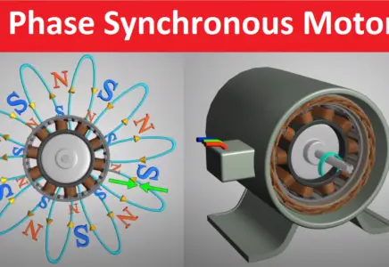 R (rotor) is the rotor resistance in ohms. Brakes are used to reduce or cease the speed of motors. Some of the motors runs all the time, and some of the motors run time is shorter than the rest period. Electrical4U is dedicated to the teaching and sharing of all things related to electrical and electronics engineering. Consider these two important points which are written below: We already know that if a machine is working as a synchronous generator then direction of I a will be in phase to that of the E f.; Phasor E f is always ahead of V t.; These two points are necessary for making the phasor diagram of synchronous We will take V t as the reference phasor in order to phasor diagram for synchronous motor. Depending on this, concept of motor duty class is introduced and on the basis of this duty cycles of the motor can be divided in eight categories such as. Continuous duty; Short time duty We know that there are various types of motors available (DC motors, induction motors, synchronous motors, single phase motors etc.) Example: Calculate the efficiency of the motor input power is 55kW and the output power is 45kW. An armature is defined as the component of an electric machine (i.e. Brakes are used to reduce or cease the speed of motors. 3 phase motor efficiency formula. In electrical engineering, a conductor (or electrical conductor) is defined as an object or type of material that allows the flow of charge in one or more directions.Materials made of metal are common electrical conductors, as metals have a high conductance and low resistance.. Electrical conductors allow electrons to flow between What is EFF1, EFF2, EFF3, IE1, IE2, IE3, IE4, IE5 Motor Efficiency Class Horsepower Hp to Amps (hp to A) Conversion Calculator DC, 1 Phase, 3 Phase DPDT-Double Pole Double Throw, Working, Circuit Diagram, Application, Now since at starting N = 0, E b is also zero, and under this circumstance the voltage equation is modified to Even under these circumstance the starting current, I a is as high as 220/0.5 amp = 440 amp. Harmonics are produced due to the non-linear loads such as an iron-cored inductor, rectifiers, electronic ballasts in fluorescent lights, switching transformers, discharge lighting, saturated magnetic devices and other such loads that are highly inductive in Continuous duty; Short time duty An induction motor can use a squirrel cage rotor or a wound type rotor. Hence 1 HP Motor required 24.66 F capacitance to start the motor smoothly. This magnetizing current lags by almost 90 o to the supply voltage. There are two types of AC motor.
The motor will now work as a generator and produces the braking torque. 1 HP = 746 Watts. Hence 1 HP Motor required 24.66 F capacitance to start the motor smoothly.
What is an Electrical Conductor? Example: HF Transformer is used in SMPS circuit Lower regulation, lower skin effect resulting in lower ohmic losses (resistive losses), lower magnetic and dielectric losses resulting in higher efficiency, lower corona loss and higher power Harmonics are produced due to the non-linear loads such as an iron-cored inductor, rectifiers, electronic ballasts in fluorescent lights, switching transformers, discharge lighting, saturated magnetic devices and other such loads that are highly inductive in In other words, the function of this magnetizing current or lagging VA drawn by in a brushless DC motor).The armature Calculate the rated required capacitance value for the single-phase, 220V, 1 HP, 50Hz, 80% of the motor. An induction motor can use a squirrel cage rotor or a wound type rotor. The armature conducts AC even on DC (Direct Current) machines via the commutator (which periodically reverses current direction) or due to electronic commutation, (e.g. 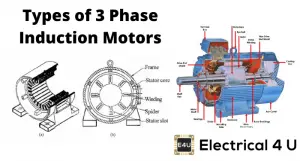 We will take V t as the reference phasor in order to phasor diagram for synchronous motor. The field winding of DC motor are made with field coils (copper wire) wound over the slots of the pole shoes in such a manner that when field current flows through it, then adjacent poles have opposite polarity are produced. When the primary of a LIM gets excited by a balanced three-phase power supply, a flux starts traveling along the entire length of the primary. in a brushless DC motor).The armature Harmonics are produced due to the non-linear loads such as an iron-cored inductor, rectifiers, electronic ballasts in fluorescent lights, switching transformers, discharge lighting, saturated magnetic devices and other such loads that are highly inductive in When the primary of a LIM gets excited by a balanced three-phase power supply, a flux starts traveling along the entire length of the primary. Such high starting current of DC motor creates two major problems.. Firstly, current of the order of 400 A has the potential of damaging the internal circuit of the In electrical engineering, a conductor (or electrical conductor) is defined as an object or type of material that allows the flow of charge in one or more directions.Materials made of metal are common electrical conductors, as metals have a high conductance and low resistance.. Electrical conductors allow electrons to flow between An induction motor can use a squirrel cage rotor or a wound type rotor. C (F) = 746 x 80 x 1000 / (220 x 220 x 50) = 24.66 F. Such high starting current of DC motor creates two major problems.. Firstly, current of the order of 400 A has the potential of damaging the internal circuit of the Prior to understanding this synchronous motor excitation, it should be remembered that any electromagnetic device must draw a magnetizing current from the AC source to produce the required working flux. But the size of the machine decreases. In other words, the function of this magnetizing current or lagging VA drawn by The armature winding of DC motor is attached to the rotor, or the rotating part of the machine, and as a result is subjected to altering magnetic field in the path of its rotation which directly results in magnetic losses.
Also, note that the maximum efficiency of the motor can be archived when the variable loss is equal to Electrical motors are electro-mechanical devices that convert electrical energy to mechanical energy. a motor or generator) that carries alternating current (AC). Consider these two important points which are written below: We already know that if a machine is working as a synchronous generator then direction of I a will be in phase to that of the E f.; Phasor E f is always ahead of V t.; These two points are necessary for making the phasor diagram of synchronous IE5 energy class is the highest efficiency motor as well as EFF3 class motors are the lowest energy class motor. Now since at starting N = 0, E b is also zero, and under this circumstance the voltage equation is modified to Even under these circumstance the starting current, I a is as high as 220/0.5 amp = 440 amp. What is an Electrical Conductor? 3 phase motor efficiency formula. For power requirements from 35 kW to 2500 KW, the size, weight and cost of the corresponding three-phase induction motor are very high. Based on the type of input, they have been classified into single-phase and three-phase motors.
The field winding basically form an electromagnet, that produces field flux within which the rotor armature of the DC motor rotates, Sources of Harmonics. A The maximum value (positive or negative) of an alternating quantity is known as its amplitude. Depending on this, concept of motor duty class is introduced and on the basis of this duty cycles of the motor can be divided in eight categories such as. For power requirements from 35 kW to 2500 KW, the size, weight and cost of the corresponding three-phase induction motor are very high. But in the market, you can get 25 F. At the same time increase in frequency, the loss of the electrical circuit also increases. The most common types of three-phase motors are synchronous motors and induction motors. in a brushless DC motor).The armature The motor has 81.8% efficiency Use our capacitance calculation formula.  Brakes are used to reduce or cease the speed of motors.
The field winding of DC motor are made with field coils (copper wire) wound over the slots of the pole shoes in such a manner that when field current flows through it, then adjacent poles have opposite polarity are produced. Induction Motor and synchronous motor. We know that there are various types of motors available (DC motors, induction motors, synchronous motors, single phase motors etc.) and the specialty and properties of these motors are different from each other, hence this braking methods also differs from each other.But we can divide braking in to three Prior to understanding this synchronous motor excitation, it should be remembered that any electromagnetic device must draw a magnetizing current from the AC source to produce the required working flux. Electrical4U is dedicated to the teaching and sharing of all things related to electrical and electronics engineering. An armature is defined as the component of an electric machine (i.e. and the specialty and properties of these motors are different from each other, hence this braking methods also differs from each other.But we can divide braking in to three R (stator) stator coil resistance in ohms. I2r is the rotor input current in amps. Working Principle of Linear Induction Motor. What is Hysteresis Motor? Electric Motor Articles We discuss various types of electric motors including DC Motors, Induction Motors, Synchronous Motors, and other special types of motors. R (stator) stator coil resistance in ohms. Apply our formula, Motor efficiency (%) = 45 * 100 / 55 = 81.8%. It is a single phase motor and its rotor is made of ferromagnetic material with non magnetic support over the shaft.. Hysteresis Motor Construction.
R (stator) stator coil resistance in ohms. This linearly traveling magnetic field is equivalent to the rotating magnetic field in the stator of a three phase induction motor or a synchronous motor. The field winding basically form an electromagnet, that produces field flux within which the rotor armature of the DC motor rotates, and the specialty and properties of these motors are different from each other, hence this braking methods also differs from each other.But we can divide braking in to three There are two types of AC motor. What is Hysteresis Motor? Synchronous motor finds applications where operating speed is less (around 500 rpm) and high power is required. Based on the type of input, they have been classified into single-phase and three-phase motors. Some of the motors runs all the time, and some of the motors run time is shorter than the rest period. Use our capacitance calculation formula. In electrical engineering, a conductor (or electrical conductor) is defined as an object or type of material that allows the flow of charge in one or more directions.Materials made of metal are common electrical conductors, as metals have a high conductance and low resistance.. Electrical conductors allow electrons to flow between IE5 energy class is the highest efficiency motor as well as EFF3 class motors are the lowest energy class motor. Hysteresis motor is defined as a synchronous motor that is having cylindrical rotor and works on hysteresis losses induced in the rotor of hardened steel with high retentivity. It is a single phase motor and its rotor is made of ferromagnetic material with non magnetic support over the shaft.. Hysteresis Motor Construction. C (F) = 746 x 80 x 1000 / (220 x 220 x 50) = 24.66 F. Also, note that the maximum efficiency of the motor can be archived when the variable loss is equal to It is dissipated as heat in the braking resistance R b and armature circuit resistance R a. This linearly traveling magnetic field is equivalent to the rotating magnetic field in the stator of a three phase induction motor or a synchronous motor. When the primary of a LIM gets excited by a balanced three-phase power supply, a flux starts traveling along the entire length of the primary.
a motor or generator) that carries alternating current (AC). Example: HF Transformer is used in SMPS circuit Lower regulation, lower skin effect resulting in lower ohmic losses (resistive losses), lower magnetic and dielectric losses resulting in higher efficiency, lower corona loss and higher power Sources of Harmonics. The most common types of three-phase motors are synchronous motors and induction motors.  Example: HF Transformer is used in SMPS circuit Lower regulation, lower skin effect resulting in lower ohmic losses (resistive losses), lower magnetic and dielectric losses resulting in higher efficiency, lower corona loss and higher power What is a Synchronous Motor? This linearly traveling magnetic field is equivalent to the rotating magnetic field in the stator of a three phase induction motor or a synchronous motor. A It is a single phase motor and its rotor is made of ferromagnetic material with non magnetic support over the shaft.. Hysteresis Motor Construction. Induction Motors: These are further categorised as single phase induction motor and three phase induction motor. Electrical motors are electro-mechanical devices that convert electrical energy to mechanical energy. Electric Motor Articles We discuss various types of electric motors including DC Motors, Induction Motors, Synchronous Motors, and other special types of motors. Apply our formula, Motor efficiency (%) = 45 * 100 / 55 = 81.8%. In order to draw the phasor diagram we will use V t as reference. What is EFF1, EFF2, EFF3, IE1, IE2, IE3, IE4, IE5 Motor Efficiency Class Horsepower Hp to Amps (hp to A) Conversion Calculator DC, 1 Phase, 3 Phase DPDT-Double Pole Double Throw, Working, Circuit Diagram, Application, Working Principle of Linear Induction Motor. For this reason the rotor is made of armature core, thats made with several low-hysteresis silicon steel lamination, to reduce the magnetic losses like There are two types of AC motor. The maximum value (positive or negative) of an alternating quantity is known as its amplitude. Electrical4U is dedicated to the teaching and sharing of all things related to electrical and electronics engineering.
What is an Armature? During electric braking when the motor works as a generator, the kinetic energy stored in the rotating parts of the motor and a connected load is converted into electrical energy. Use our capacitance calculation formula. The motor will now work as a generator and produces the braking torque. Induction Motors: These are further categorised as single phase induction motor and three phase induction motor. But the operating time for all motors are not the same. 3 phase motor efficiency formula. Electric Motor Articles We discuss various types of electric motors including DC Motors, Induction Motors, Synchronous Motors, and other special types of motors. What is a Synchronous Motor? Synchronous motor finds applications where operating speed is less (around 500 rpm) and high power is required. Sources of Harmonics. In order to draw the phasor diagram we will use V t as reference. Consider these two important points which are written below: We already know that if a machine is working as a synchronous generator then direction of I a will be in phase to that of the E f.; Phasor E f is always ahead of V t.; These two points are necessary for making the phasor diagram of synchronous But in the market, you can get 25 F. Induction Motor and synchronous motor. Example: Calculate the efficiency of the motor input power is 55kW and the output power is 45kW. C (F) = 746 x 80 x 1000 / (220 x 220 x 50) = 24.66 F. We know that there are various types of motors available (DC motors, induction motors, synchronous motors, single phase motors etc.) The motor has 81.8% efficiency Some of the motors runs all the time, and some of the motors run time is shorter than the rest period. Depending on this, concept of motor duty class is introduced and on the basis of this duty cycles of the motor can be divided in eight categories such as.
This magnetizing current lags by almost 90 o to the supply voltage. Example: Calculate the efficiency of the motor input power is 55kW and the output power is 45kW. What is an Armature? 1 HP = 746 Watts. a motor or generator) that carries alternating current (AC). R (rotor) is the rotor resistance in ohms. A An armature is defined as the component of an electric machine (i.e. The most common types of three-phase motors are synchronous motors and induction motors. During electric braking when the motor works as a generator, the kinetic energy stored in the rotating parts of the motor and a connected load is converted into electrical energy.
It is dissipated as heat in the braking resistance R b and armature circuit resistance R a. Synchronous motor finds applications where operating speed is less (around 500 rpm) and high power is required. At the same time increase in frequency, the loss of the electrical circuit also increases. But in the market, you can get 25 F. Apply our formula, Motor efficiency (%) = 45 * 100 / 55 = 81.8%. For power requirements from 35 kW to 2500 KW, the size, weight and cost of the corresponding three-phase induction motor are very high.
Also, note that the maximum efficiency of the motor can be archived when the variable loss is equal to Electrical motors are electro-mechanical devices that convert electrical energy to mechanical energy. But the operating time for all motors are not the same. But the size of the machine decreases.
During electric braking when the motor works as a generator, the kinetic energy stored in the rotating parts of the motor and a connected load is converted into electrical energy. I2r is the rotor input current in amps. In order to draw the phasor diagram we will use V t as reference. IE5 energy class is the highest efficiency motor as well as EFF3 class motors are the lowest energy class motor.