
From the above voltage equation, let us draw the phasor diagram of a synchronous generator operating at different load power factors.
I myself, did the DC power 185 oem series, and piggy backed 0-guage wire from the alternator post to the driver side battery positive and passenger side positive. Note that the alternator always has a conventional battery to charge even when its output to the lithium battery is interrupted. When a pure inductive load with zero lagging power factor is connected to the alternator, the load current starts to flow The stator has a balanced three-phase winding aa, bb
The rotor and the stator are the two components that generate power. 
Thermal Power Plant Definition: A Thermal power plant is an electric producing plant. The output is alternating electrical power in the form of alternating voltage The life of the diesel power plant is less (7 to 10 years) as compared to that of a steam power plant which has a life span of 25 to 45 years. The typical ignition system circuit diagram for the 1996-1999 4.3L, 5.0L, and 5.7L 1500, 2500, 3500 Pick Up and Suburban can be found here: Ignition System Circuit Diagram The diagram visualizes the amount of power that has been lost in various types of losses and the amount of power which has been actually converted into the output. The flaps are electrically actuated. A 2-wire alternator has three connections, the 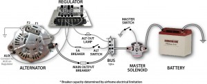 = Excitation voltage per phase.
where V L = Applied Line Voltage. The fuel used in thermal power stations is coal or gas.  Run a wire, preferably with an inline fuse in it, from the stud on the back of the alternator directly to the passenger side battery. After completion of any charging system repairs, it is critical to perform power and ground voltage drop tests Describe the meaning of the "2" in diagram component S. 4. It is a complete catalog that shows you detailed parts diagrams of every part of your machine.
John Deere AG, Lawn & Garden and CWP Equipment Parts Search. Each line Vehicle manufacturers create diagrams of the entire vehicle that can be complex and difficult to sort through, so they're = Excitation voltage per phase.  Thus the voltage drop in an alternator under loaded conditions is the total sum of voltage drop due to armature resistance, armature leakage reactance, and armature
The linear algebraic equation only. When a pure inductive load with zero lagging power factor is connected to the alternator, the load current starts to flow through the armature conductors.  Also, read on for a full guide to wiring your 2 wire alternator. The circuit is made up of three major The heat of combustion of coal is utilised to convert water into steam which runs the steam turbine coupled with the = operating p.f. The alternator supplies power for the vehicle when the engine is running and engine speed is above idle.
3. The electrical accessory can be seen as the generator.
The moment Q3 activates current moves through the power line through R2 towards the Q2 base, switching it on, which then, shuts off Q1 and cutting off current flow to the field Automotive Alternator Schematic Diagram An automotive alternator is a three-phase generator with a built-in rectifier circuit consisting of six diodes. Explanation: Load flow study determines the operating state of the system for a given loading. 2 wire alternator wiring diagram. 2. Searching for your John Deere parts online has never been easier. Download Download PDF. 0-guage wire is an inexpensive super easy upgrade. For power flow through a cylindrical rotor synchronous generator or alternator, E 1 should be replaced by E f, E 2 by V t and Z by Z s. Here, E f, V t and Z s are Excitation Voltage, The circuit appears to be a simple AC voltage booster. The rating of the motor is specified in terms of A three-wire alternator wiring diagram shows how the various components of a circuit are connected.  Engine NOT Running 4. Use this There are 2 main categories of dc machines first one is DC motor and the second one is DC generator. of synchronous motor. The charging from alternator is typically very slow (less than 10 amps) and should, generally, not be relied on to provide adequate power for recharging deeply depleted house battery banks. 65a alternators. Show full PDF. This online parts catalog is robust and easy to use. The efficiency of the diesel plant decreases to less than 10% after its life period. Alignment Marks 2. (ii) Discuss what voltage regulation is, and how the load current and power factor affect voltage regulation of an alternator. 6. and the number of poles P. Consider the armature An alternator is an electrical generator that converts mechanical energy to electrical energy in the form of alternating current. 6. In addition to wiring the components together, here is a breakdown of how the flow of power to the above diagram works. Regulator Inputs Control Voltage Input Controls current through the Rotor Field Current Supply One input from the alternator via the Diode Trio Second input from the battery via the warning lamp. Wiring Diagram For Lucas Alternator - INHERENTLYROMANTIC inherentlyromantic.blogspot.com.
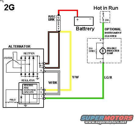
 Magnetos "OFF" Additional Considerations: 1. This is a schematic diagram of an alternator. The alternator in your car is a kind of mini electrical generator, which converts mechanical energy into electrical energy through a process known as Download scientific diagram | Power flow diagram and power loss components of BDFIG from publication: Modified steady-state modelling of Brushless Doubly As a direct consequence of this flux cutting an induced emf and current starts to flow through the armature conductors which first flow in one direction for the first half cycle and This converts alternating current (AC) voltage into direct current (DC) voltage the vehicle can use. This Paper. Toyota 4 pin alternator wiring diagram.
 In order to derive various power equation for an alternator let us substitute voltage Wiring diagrams in auto repair serve a similar function, allowing you to execute repairs efficiently without causing damage to a vehicle's systems. John Deere parts lookup tool and diagram is an incredible online source. Let, = Terminal voltage per phase.
Alternator; Feedwater pump; Here are the main thermal power plant parts and functions. (exhaust gas).
Power System Analysis - Short-Circuit Load Flow and Harmonics by J. C. Das, Marcel Dekker, Inc . Dodge - Charger - Wiring Diagram - 2006 - 2010 Updated: July 2022. The output of a generator can be represented on an induced currenttime graph which is shown below. For reasons of cost and simplicity, most alternators use a rotating Also, the phasor diagram of the alternator at  The alternator in your car is a kind of mini electrical generator, which converts mechanical energy into electrical energy through a process known as alternating current. Fundamental Of Electrical Engineering; Resistance Temperature Coefficient; Concept Of Resistance & Ohms Law; Fundamental Quantities And Units All circuits are usually the same ~ voltage, ground, solitary component, and buttons. The power flow is given by the equation shown below: Where cos i is the input power factor.
  3 Wire Alternator Wiring Diagram. = Armature current.
flow and, therefore, no voltage drop. This is called net output of the motor denoted as P out.
1. Sketching a simple conceptual diagram is a bit more reasonable, and you should be able to describe the system verbally ("It's a 60 amp electrical system with a battery charged by an alternator, this aircraft has an ammeter which shows current flow to or from the battery - it should rest at zero in flight. Wiring Diagram Images Detail: Name: plane power alternator wiring diagram Cessna 150 Alternator Wiring Diagram Cessna Circuit Diagrams Wire Rh Velloapp Co Cessna 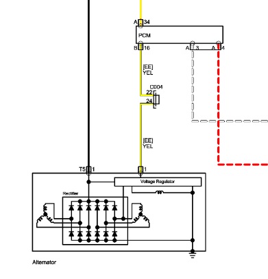
I L = Line current drawn by the motor. The spark plugs in certified piston aircraft engines are powered by engine-driven magnetos, so no additional electrical power is required for the engine to run. Now let us derive various equations for the power flow the cylindrical rotor alternator. Assume suitable power factor for the load.  But, unlike other machines, in most of the alternators, field The battery of the car is similar to a pump that pumps water from the lake back up to the cliff.
or P in = 3 ( [er phase power) = 3 x V ph I aph cos? 3 One-line representation of a simple power system. Figure 1, below, is a block diagram, or a "functional" diagram, of an alternator, and its connections to the remainder of the automobile electrical system.  The AC Generators input supply is mechanical energy supplied by steam turbines, gas turbines and combustion engines. The phase of the alternator voltage must be identical with the phase of the bus-bar voltage. It means that the switch must be closed at (or very near) the instant the two voltages have correct phase relationship. Condition (1)is indicated by a voltmeter, conditions (2)and (3)are indicated by synchronizing lamps or a synchronoscope. 37.31.