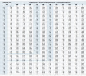
The power factor can be improved by providing K V A R to the inductive type loads and to provide the K V A Rs we can use a capacitor. e.g., Variable frequency drives typically have very high PF D values. Power factor improvement using capacitors is achieved by using static capacitors. The first step is to measure to determine the root cause of bad power factor is measurement. = 400 x .403 (Table 3) = 161.2. In the table 1 above, at the intersection between the row initial cos 0.75 with the column final cos 0.9, a value of 0.398 for the coefficient K is obtained. Know about the 3 most commonly used ways of improving power factor i.e. For Power factor improvement purpose, Static capacitors are connected in parallel with those devices which work on low power factor. A 90 % leading power factor would indicate a capacitive load in which the current leads the voltage by an angle with a cosine of 0.9, or approximately 26 o. The total I 2 drawn from the supply will be equal to the phasor sum of I 1 and I c that is. Question added by Muhammad Ramzan , student , University Of Gujrat Date Posted: 2016/03/23. Power factor penalty charge per month = 227.98 x 720 x 29,546.2. Just like capacitors coils store energy and emit that energy later. Considering first the DC circuits, having only DC voltage sources, the inductors and capacitors behave as short circuits and open circuits respectively in steady-state.. 
 Improve power factor using these 3 ways. Power factor penalty charge per month = 64.09 x 720 x 8,306.06.
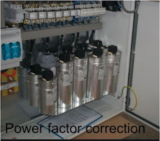
This can reduce electric bill and lower ohmic losses in transformers and wiring. These capacitors provide varying amounts of power factor correction to address the entire facility. Well use the same 5,000 kW load, and 3,750,000 kWh per month electricity consumption. This process will improve the efficiency of electrical supply, in this way less electrical energy is used to accomplish the same tasks. Capacitor power calculation table Conversion table. For a capacitor.
To improve the power factor static capacitors are connected in parallel with those devices which work on low power factor. The low PF is mainly due to the fact that most of the power loads are inductive and, therefore, take lagging currents. You will get 292 KVAR. Methods of power factor improvement. Example of Power Factor Charge PF Charge Factor NC Charge $0.40 kW Charge $10.25 Max Billing kW 8.592 kWh Charge $0.03854 Power Factor 0.79 Calc kVA 10.8759 kW 8.6 Calc kVAR 6.6681 kWh 2064 In AC power supplies Capacitor Banks are mainly used to improve the power factor of the AC Loads. Which load power factor is improved by using capacitor? Power Factor correction capacitor formula. Static capacitors whose ratings vary from 15 kvar to 10000 kvar are used as devices to improve or correct power factor of the system. There are a number of options to choose from when applying capacitors to increase power factor.
As a capacitor is generator of reactive power, therefore the lagging reactive power demand of the equipment is locally supplied by the static capacitor. Looking at power line poles you will occasionally see a group of rectangular boxes mounted high in the pole. This is because the ripple current rating of a capacitor does not increase linearly with size and there may also be height limitations. As an example: To improve the power factor of a 400 KW load from .77 to .92 : KVAR = KW x Multiplier.
2.we can connect the reactor in parallel to avoid the increasing of voltage These are capacitors being used for power factor correction. cos1 original power factor. Power Factor Correction How to correct power factor with a capacitor. A motor requires inductive or lagging reactive power for magnetizing. By reducing the reactive component of power the load current drawn by the system is reduced. Increases energy efficiency.By optimizing the power factor, your power quality increases improving performance and reducing unplanned outages which lessen potential damage to your electrical network. A capacitor freely supplies the distribution system with what is called a Leading reactive power compared to the Lagging reactive power supplied by the utility company. Thus the p.f is improved. The power factor correction can be done by the following two methods: Power Factor Correction Method using Capacitors; Power Factor Correction Method using a Synchronous Condenser; Power Factor Correction by Capacitor Banks. When power factor is 1, it means all power supplied by source is being consumed. Figure 5. More the inductive the circuit nature is, more energy losses and less power factor. KVAR2 = 560*(1-0.952) KVAR2 = 175. Our calculator just implements the above formula. Weve added a power-factor-correction capacitor in parallel with the original circuit. There are a number of options to choose from when applying capacitors to increase power factor. Power factor, Pf =cos . The capacitor achieves this by storing the magnetic reversal energy. How to improve power factor? To improve the power factor of an installation generally a capacitor bank is used. __________________.
Now, subtract KVAR1 by KVAR2. communities including Stack Overflow, the largest, most trusted online community for developers learn, share their knowledge, and build their careers. The two most common contributors to poor power factor are motor inductance and harmonic currents. Capacitors as kVAR generators Figure 7. To determine the unknown reactive power triangle quantity we use the pythagorean theorem backwards given the length of the hypotenuse apparent power and the length of the adjacent side true power. Power factor can be corrected by connecting a static capacitor in parallel with the load taking lagging reactive power. This and other ways of increasing power factor are listed below: 1. Figure 7 shows an inductive load with a power factor correction capacitor. The ratio of V/ I = 1/(wC) is the capacitor impedance. 1.we can connect the capacitor in parallel to improve the power factor. It is necessary to improve the performance of electrical system and maintains power factor at higher value. Required apparent power before and after adding capacitors 18 A 16 A 10 hp, 480 V motor at 84% power factor 3.6 A 3 kVAR Capacitor Power factor improved to 95% Required Apparent Power Before and After Adding Capacitors 18A 16A 10 hp, 480V Motor at 84% Power Factor 3.6A 3 kVAR Capacitor Power Factor Improved to 95% P (kW)=HP0.746/, where is efficiency in decimal (typically 0.8 to 0.95). In the above example, 161.2 KVAR would be required to correct the complete system. The Power factor decreases with an increase in lag or lead of current from the voltage. How to improve power factor using capacitors. . With capacitors in the electrical distribution system, the reactive powers cancel each other out Capacitor sizing for power factor correction - Electrical A poor power factor is usually caused by coils; by inductors within electric motors. Here, well do a second round of calculations with capacitors. Capacitor Bank is an assembly of capacitors which has the same rating arranged in series or parallel. Power factor. The process of improving power factor is called power factor correction. There are many power factor correction methods. Low power factor means lower operating efficiency which results in a need for larger conductors (wires) and increased equipment capacity, as well as causing voltage drops as power losses increase. How to improve power factor using capacitors. In modern power network, a wide variety of electrical load and power electronics load, which create a varying power demand on the supply system and less power distribution leads to loss of energy. Static capacitors provide leading current that neutralizes the lagging inductive component of load current. Using VFDs to drive induction motors can improve power factor but it's not the panacea that some manufacturers suggest. Since in capacitors the current leads the voltage, they can increase the overall PF by introducing a counteracting current. You can use this value to purchase the exact capacitor so as you would get the desired value of power factor. It also gives the equivalence between cos and tg . The transformer utilization factor (TUF) of a rectifier circuit is defined as the ratio of the DC power available at the input resistor to the AC rating of the output coil of a transformer. 2.we can connect the reactor in parallel to avoid the increasing of voltage This is because the DC bus capacitors supply the necessary reactive current to the motor for inducing the rotor's magnetic field, and the AC supply line. Saves energy.Energy loss can be reduced by up to 30% depending on the level of capacitor compensation. When we read the power transmission or Circuit Theory,the book will teach us two things . However with the addition of non-linear load types there has been an exponential increase in the number of power factor correction capacitors failures and fires. Hi: The best way to improve power factor (usually lagging with an inductive load) is by the addition of capacitance. Capacitors improve power factor by drawing current 180 degrees out of phase with the 90 degree lagging reactive current component of the system. The ideal solution is to match inductance with capacitance to keep the current and voltage in balance. Our power-factor-corrected system is equivalent to the following circuit: Figure 4. capacitor banks, synchronous condenser & Phase advancer. Why improve low power factor? 1 Introduction The power factor of an AC electrical power system is de ned as the ratio of the real power owing to the load to the apparent power in the circuit. The ways to improve power factor are nothing but the ways to generate equal and opposite reactive power. The caps will supply certain reactive power to the machine, so the facility doesn't have to draw it all the way from the utility station. The ideal solution is to match inductance with capacitance to keep the current and voltage in balance. I2 R Losses. How to correct power factor with a capacitor. I = A(C)w cos wt = A(C)w sin (wt + 90) I leads V by 90 degrees. Thus, it comes as no surprise that one way to increase the PF is to add capacitors to the system. Conclusions. Calculating capacitor size to improve power factor to 0.95 This is called resonance condition. Calculate the value of KVAR using desired value of power factor. By installing power capacitors and increasing power factor to 95%, apparent power is reduced from 142 kVA to 105 kVAa reduction of 35%.
Methods of power factor improvement. In AC power supplies Capacitor Banks are mainly used to improve the power factor of the AC Loads. Power Factor Correction Methods. Figure 6. Some of the more common approaches are as follows: 2 show how capacitors can improve the power factor Re: Power Consumption of a Capacitor. Ideal power consumption of a capacitor is Zero. For other parts, you can just check up the electrical parameters ( use a megger). Re: Power Consumption of a Capacitor. Download this - it has all your answers and is far too much for me to type. Location: N. Texas, U.S.A., et al from time to time. The Power factor decreases with an increase in lag or lead of current from the voltage. Variable frequency drives typically have very high PF D values. As the reactive power is inductive, well add a capacitor in parallel with the load. Before discussing about the improvement of power factor by using capacitor, we should recall the general knowledge of Apparent Power, Active Power and Reactive Power. Three most commonly used ways are Capacitors or capacitor banks Figure 6. You pay a minimum of more energy loss (in the capacitor) and get rid of a much higher energy loss (in the supply system). In the above example, 161.2 KVAR would be required to correct the complete system. When. If there are excessive harmonics in the current the situation can change. Top 3 Ways to Improve Power FactorCapacitors or capacitor banks. For power factor correction, capacitor or capacitor banks is the most commonly used method. Synchronous condenser. When a Synchronous motor operates at No-Load and over-exited then its called a synchronous Condenser.Phase Advancer. Phase advancer are mainly used to improve power factor of induction motors. Summary. The power triangles in Fig. Using the Power factor correction capacitors in parallel with the circuit is the easiest way to improve the power factor. To determine the unknown (reactive power) triangle quantity, we use the Pythagorean Theorem backwards, given the length of the hypotenuse (apparent power) and the length of the adjacent side (true power): How to Correct Power Factor with a Capacitor. By reducing the reactive component of power the load current drawn by the system is reduced. how adding capacitors to AC power circuit helps improve power factor. These static capacitors provides leading current which neutralize (totally or approximately) the lagging inductive component of load current (i.e. 06/11/2008 8:20 AM. A capacitor is the opposite of a coil, and can improve the Substituting 1 and 2 into our expression for Qc we get: where PF 1 and PF 2 are initial and improved PF respectively (if you have PF expressed in percentage, you need to divide it by 100). 1.we can connect the capacitor in parallel to improve the power factor. Power Factor Correction Capacitors directions and one may increase cost.