By Petr Chmel?ek. 4 shows the corresponding generator vector diagram. F = Frequency in hertz. 4. Summary The base power may be the rating of a single piece of apparatus such as a motor or generator. In the absence of other information, (for 60 Hz systems). The synchronous generator reactance of 12.5% could be X"d [subtransient reactance] but only if it is a salient poles machine. K. Webb ESE 470 11 Sub-Transient Fault Current Transition rates between reactance values are dictated by two time constants: : short-circuit subtransient time constant : short-circuit transient time constant Neglecting generator resistance, i.e. Three Phase P.F Calculation Calculation with Line to Line Voltage (V L-L) Cos = kW / (3 x V L-L x I) Calculation with Line to Neutral Voltage (V L-N) Cos = kW / 3 x V L-N x I C= Capacitance in farads. The circuit breaker should be capable of Breaking & Making current as per their ratings & should also have Rated short time capacity. So, Its rotation speed is known as synchronous speed because its rotation speed equals the speed of rotation of field at stator that known as synchronous speed. Online computer and formulas for the calculation of voltages and power in a series circuit of capacitor currents, impedance and reactance of a series circuit consisting of a resistor and a capacitor. Learn More: kW to Cable Size Chart & Electrical Cable Size Chart Amps. 3.Transformer: 15 MVA, 5% reactance, 11/33KV. Determine gen-set size for three loads started across-the-line in a single step. Viewed 4k times 0 \$\begingroup\$ What's the formula for calculating generators internal resistance in a circuit with a load? Most of the time you will have to get this value from the generator manufacturer. The governor set points of the generator control the real power (P) supplied by the generator to the system.  Reactances are used to describe the behavior of a generator during certain operating conditions. Your Home. Fault Level Calculation 1. Its SI unit is the watt.. The subtransient reactance is an impedance value that entirely neglects the resistance component. Its an important quantity to know because a generators short-circuit current is calculated from its subtransient reactance . The current produced due to subtransient reactance is relevant to choosing a circuit breakers instantaneous trip setting. HMC5883L 3-Axis Compass Module Arduino interfacemagneto-resistive sensors arranged in axes perpendicular to each other.Pin connection of the module with ArduinoConventional bearing arduino compassrepresented as N, E, S, W directionsN 45 E But, the generator armature reactance is such a large part of its total impedance that resistance is ignored. Start by simply inputting your home's postal code, square footage and choose your unique power requirements below. Modified 5 years, 5 months ago. Abstract. So, if the minimum tolerated voltage distortion is 25%, (typical soft starter), then Xddist = (0.36 x 25%) = 9%. Re: Subtransient Reactance of Generator. 8.11 with switch S open. Generator constants: X d = X 1 = X 2 = 15% ; X 0 = 5% 1. I am getting 4040A where SKM is giving me about 2499A. Xd' unsat means unsaturated transient synchronous reactance where as Xd"sat means saturated sub_transient synchronous reactance. Generally, the load connected to the alternator is of inductive type. All electrical loads are different just as generators, it is always best to oversize a generator to the electrical load.
  8.11 with switch S open.
  Reactance (Xd) To calculate Xd in Voltage drop E VD = IR cos + IX sin where abbreviations are same as below Exact Method. Z = Impedance (Resistance in AC circuits i.e. For example, generator reactances in per unit are similar for both 100 MVA machines and 1000MVA machines. See ABB Switchgear Manual 11 ed. Display the answer in ohms.
  As Example: An inductor of 55mH, has a frequency of 50Hz, which is its inductive reactance, to find the answer it must be multiplied: 2xx50x55x10 ^ -3 = 17,28Ohm. Cos = kW / kVA.
xo / 100 . 2. Search: Generator Load Calculation Formula. 1.Generator-A: 10 MVA, 10% reactance. Note that in FIGURE 2 the generator reactance shown in series with ground is the zero sequence reactance. In synchronous machines the knowledge of reactances values, Under normal operation, the saturated synchronous reactance \(X_S=0.4\Omega\) and \(R_A\) is negligible. We created this generator size calculator to help you consider your needs and to help you think about what you would like to power during an outage at your home. Capacitive reactance equals to reciprocal of 6.28 product of frequency (which is indicated as F) in hertz and capacitance (which is indicated as C) XC= 1/2fC. 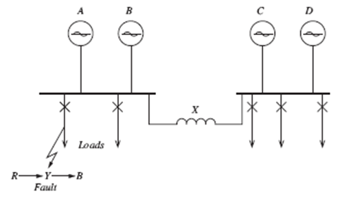 The Smith chart, invented by Phillip H. Smith (19051987) and independently by Mizuhashi Tosaku, is a graphical calculator or nomogram designed for electrical and electronics engineers specializing in radio frequency (RF) engineering to assist in solving problems with transmission lines and matching circuits. Calculate the Generator Reactance. How to calculate the fault current for a generator? Formula Load Calculation Generator . In this figure, is the internal angle between the excitation voltage and the generator terminal voltage.
  Where. A useful approximation of the generator subtransient reactance, Xddist, necessary when a 6pulse soft starter is used to accelerate a motor, is 0.36 x tolerated voltage distortion. S Where : - S : Apparent Power - Un : Voltage between 2 phases Using an oversize generator to reduce reactance may be of some benefit. Table 9C-1 Calculations for Electrical Design Calculation Description Required Tools1 Reqd All Reqd Cond2 By Engr3 By Cntr3 Design Phase (%) Load - facility, switchgear, MCC I am given the load resistance and the voltage sources voltage. The reactive power oscillates back and forth between the capacitor and the generator. 2. ch. However, the values of the Potier reactance of synchronous machines measured at the rated terminal voltage can be much larger than those of the armature leakage reactances [1]. C= Capacitance in farads. Search: Generator Load Calculation Formula. 4.Transmission Line: Impedance Z = 5+j20 ohms. Where: = 2 and the output voltage Vout is a constant 1/RC times the integral of the input voltage V IN with respect to time. (15 percent), based on 25,000 kVA and Grounding is the connection between live parts of a machine (which carries current in normal operation) and earth such as the neutral of a generator or neutral point of a star connected power transformer.
  The equivalent resistance, impedance, and leakage reactance are known by the short circuit test. REACTANCES It can be defined as the imaginary part of the impedance in any power circuit. Example One calculation. Were.
 What is Grounding? A four pole, three-phase synchronous generator is rated 250 MVA, its terminal voltage is 24 kV, the synchronous reactance is: 125%. A cylinder rotor generator delivers 0.5 pu power in the steady state to an infinite bus through a transmission line of reactance 0.5 pu. Add the two numbers together for total watts needed.
  S - Synchronous Reactance : Xo = Un^2 . xd / 100 . FAULT LEVEL CALCULATION Dinesh Kumar Sarda 2. R g +jX g = R a +jX d = 0.02+j0.25 pu Power Suite is a free, industry leading online tool for power system product sizing and specification generation.
 The generator no-load voltage is 1.5 pu and the infinite bus voltage is 1 pu. Cos = Power Factor; kW = Real Power in Watts; kVA = Apparent Power in Volt-Amperes or Watts; Additional formulas used for power factor. For prefabricated bus-trunking and similar pre-wired ducting systems, the manufacturer should be consulted.

2.Generator-B: 5 MVA, 7.5% reactance. Calculate the unsaturated synchronous reactance; The generator is operating at 500kVA with power factor 0.9 lagging.
3.
Ln = Equivalent reactance of NGR. Subscripts G Generator. For example, if the base value of voltage had been selected as 13,800 V and the present value is 11,000 V, the value of voltage per unit is VPU = 11,000 13,800 = 0.797 PU, or VPU = 0.797 (100) = 79.7% PU At the capacitive reactance of the capacitor, the voltage lags the current by -90 . 480 volt alternator on a 750 kW DFHA generator set. 3 Calculation of Short-Circuit Currents in Three- Phase Systems. Armature Reaction Reactance (X a) : In an alternator or synchronous generator in addition to the armature winding resistance drop and leakage reactance drop, there is a drop in terminal voltage due to armature reaction. Alternator 15 MVA Voltage U = 10 kV Xd = 20% Type test is inclusive of all routine tests along with some additional tests. I forgot the phase-to-ground short-circuit. For phase-to-ground short-circuit we need Z2. X2=(X"d+X"q)/2 Find the subtransient single line-to-ground fault current in the generator windings. Hello, our today's video shows with example how to calculate short circuit contribution by an industrial generator in case of a fault in the power system. Unsaturated reactance values can be determined by application of short-circuit tests to synchronous generators, excited to reduced terminal voltages of up to 20%. In this region it can be expected that the relation between applied test voltages and resulting short-circuit currents is linear, i.e. wnu.sido.puglia.it; Views: 17855: Published: 15.07.2022: Author: wnu.sido.puglia.it: Search: table of content. 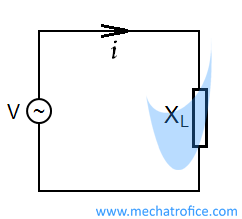 \(V_{r}\) is the generator rated voltage in V. The sum of the detail in the section is therefore; a combined multiplier for reactance The following synchronous generator & alternator formulas and equations can be used to design, simplify, and analyze the basic AC generators circuits to determine the generated voltage and EMF, speed & frequency, efficiency, voltage & current, generated power and losses etc. If sending end voltage and load PF are known. The field current in the generator controls the reactive power (Q) supplied by the generator to the system. A high power factor shows that the electrical system's electricity is being utilized efficiently. The reactance phenomenon happens with an alternating current. 2. Draw the equivalent circuit. REACTANCES It can be defined as the imaginary part of the impedance in any power circuit. From this figure, the interior impedance of the generator is given here. 2.
 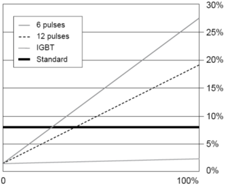 Z1 = positive-sequence impedance of the generator. less than 50 mm2 reactance may be ignored. Generator is rated 312kVA and subtransient reactance is .093pu. In adding to what Mr. Ole said, we can calculate these Reactances by using the following formulas : - Sub-Transient Reactance : Xd = Un^2 . The inductive reactance calculator is a tool to calculate the reactance of the inductor.
We simply divide the rated current with sub-transient reactance of 16.3% and get the generator short circuit contribution, which is 4945 amperes. The frequency and terminal voltage of the generator are controlled by the system to which it is connected.  Lets say an alternator with standard Winding 311/312 has reactance values published at 480V 60Hz, but the alternator is to be operated at 380V 60Hz. To learn how to calculate resistance and reactance, read on! Approximate method. Delivered power for the round-rotor machine. Download PDF. For this Network find the short circuit MVA and fault current values fed to the symmetrical fault between phases if it occurs at points F1 and F2 that is The governor set points of the generator control the real power (P) supplied by the generator to the system. where V n =voltage to neutral in volts = phase voltages in volts C A system with a low power factor wastes energy by inefficiently consuming the incoming power supply. I'm not pretending to be an "expert" in Electrical Power System Analysis. So, simplifying the basic equations I think we may say the following: Ik= Search: Generator Load Calculation Formula. Take the square root of the sum of the squares of R and X to get impedance. To find the value of an inductor that has the specified reactance at a given frequency, enter the reactance and a frequency. How to calculate the inductive reactance in 1 single step: Step 1: To calculate the inductive reactance of an inductor, multiply 2 by the number pi (), by frequency and inductance. Synchronous generators produce constant-frequency power and can operate at both leading and lagging power factors. Under normal operation, the saturated synchronous reactance \(X_S=0.4\Omega\) and \(R_A\) is negligible. Square both R and X, and add the two products together. Zsc Network upstream impedance for a three-phase fault. Exact method #1. If not the switch will fail MOTOR FULL -LOAD AMPERES Basic Fan Laws Variation Fan Speed Change Density Change Volume Varies Directly with Speed R atio %(/ 6 L %(/ 5 @ It can be shown that the synchronous speed of a motor is determined by the following formula: where n s is the (synchronous) speed of the rotor It also houses a deep library of technical information including webinars, technical papers, and presentations to help you select the right power generation products and identify facility design and installation requirements right for your project. Recommendation. Remember that although the reactance value carries units of Ohms (), and the reactance value can be used to find the. X L, X C and R known as Inductive reactance, capacitive reactance and resistance respectively). Were. Ask Question Asked 5 years, 5 months ago. The short circuit test is performed on the secondary or high voltage winding of the transformer. Example: a capacitor of 320nF, has a frequency of 1kHz, which will be the capacitive reactance, to find it you must multiply 2x320xx10 ^ -9 1000 = 0.002010624 and the result is divided as follows: 1 / 0.00064 = 497.36 Ohm. For turbo-generators this rating is low standard values of 10% and 15% of the generator continuous rating have been adopted. There are various Reactances and Time Constants which contribute during the selection of control systems and protection scheme for any Generator. If system reactance is given in percent, use Eq. The above equations can be applied to any generator which carries unbalanced currents and are the starting point for calculations for any type of fault. The base kVA rating of the 750DFHA is 938 kVA.
 suffix d represents direct axis values. The reactance of NGR required for compensation of the capacitive reactance during fault condition as shown in Fig. Example One calculation. Formula. F = Frequency in hertz. 6 - Motors At the instant of short-circuit, a running motor will act (for a brief period) as a generator, and feed current into the fault. 2. To calculate impedance, calculate resistance and reactance of a circuit, label resistance as R and reactance as X. 1. Search: Generator Load Calculation Formula.
 For example, a 1 uF capacitor or a 25.3 mH inductor will have 159 Ohms of reactance at a frequency of 1000 Hertz.Press Reset before doing a new calculation. By Meetty Tomy [Padiyar, K. R.] Power System Dynamics Stability (BookZZ.org) By deep sun. assuming =90, the synchronous portion of the fault current is = 2 3. Alternator and Synchronous Generator Formulas & Equations. Determine gen-set size for three loads started across-the-line in a single step. Thus the circuit has the transfer function of an inverting integrator with the gain constant of -1/RC. A second use for generator reactances are in specifications that limit the sub-transient reactance to 12% or less in order to limit the voltage distortion induced by non-linear loads. As was mentioned before, the angle of this power triangle graphically indicates the ratio between the amount of dissipated (or consumed) power and the amount of absorbed/returned power. This facilitates data checking and hand calculations.
  The minus sign ( ) indicates a 180 o phase shift because the input signal is connected directly to the inverting input terminal of the operational amplifier. xd / 100 . From the generator set specification sheet, S-1132, the alternator data sheet is ADS-311. What's next? Impedance Z = \[\frac{V}{I}\] Z = R + X. Isc = Ir / Xsc Xsc Short-circuit reactance c/c The most common values for a synchronous generator are: Example Calculation method for an alternator or a synchronous motor. We proposed a method to calculate d- and x-axis reactance with regard to the influence of magnetic saturation by modifying the way in which step voltage is applied in a dc test with dc current flowing between terminals of armature winding. Synchronous reactance is the generators steady-state reactance caused by a combination of the armature winding leakage reactance plus the reactance used to represent the armature reaction to a short circuit.
  The Salient Poles Synchronous Generator Rotor [inductor] magnetic field is deformed by stator [induced] reaction field. Mathematically we can deco XC = Capacitive reactance in ohms. About; Press; Blog; Includes calculation example. The value of Short Circuit Ratio varies from 0.5 to 0.8 for Turbo Generator, 1 to 1.4 for Hydro generator and 0.4 to 0.5 for synchronous condenser. If each conductor can carry 250 A and if flux/pole is 0 Our generator sizing calculator will give you a reliable kW rating When static, the load remains constant and doesn't change over time 64 N-m) o Stress Calculation- 2 2 1/ 2 max [(8 ) 48 ] 4 M Fd T d Our main categories of free calculator online are health, education, finance, informative
Consequently, nonlinear loads may work fine on utility, but may react entirely different when powered by a generator set. Calculate the rated current and the line to ground terminal voltage. We could simply calculate the reactance value at 380V by [380/480] x value at 480V = value at 380V. Generators may have 5 to 100 times greater subtransient reactance than normal source transformers . As shown in Figure 9, in the linear part of the open circuit voltage curve, the unsaturated synchronous reactance is constant. Calculate the induced voltage, E. f (Ans: X It is caused by the generated alternating flux in the transformer core. Discussion on how to calculate/convert alternator subtransient reactance X'' to generator subtransient reactance.  Impedance is a vector, or two-dimensional quantity, consisting of resistance and reactance (reaction of a built-up electric field to a change of current). 2.
Learn Basic Electrical Engineering, Protection Switch gear, relays, Online Calculator, Electrical - Get More Electrical Knowledge with easy English, Electrical Calculator ; Xs= E A /I A = V ,oc /I A. Square both R and X, and sum the two products together. This grounding provides an effective path to the fault currents from the equipment to the power source which leads to protect the power system installations and The reactance phenomenon happens with an alternating current. Fault level at any given point of the Electric Power Supply Network is the maximum current that would flow in case of a short circuit fault at that point. It is assumed in this calculation that during motor starting, the initial source emf calculated in Step 5 remains constant; that is, the power source does not react during the transient period. From the characteristics, the unsaturated synchronous impedance is given by, $$\mathrm{_{} =\frac{_{}}{_{}}= _{} + _{}}$$. In a Perfect theoretical Scenario it should be 1. Short Circuit Ratio can easily be obtained from the Open Circuit (OCC) and Short Circuit Characteristics (SCC) of Synchronous machine. System base kVA = Generator kVA = 3125 System base voltage at the switchboard = 13,800 volts System base voltage at the MCC = 13,800transformer ratio = 13,800 4000 13,200 = 4181.8 volts, b) The system base value of the generator impedance R g +jX g is the same as that for the generator kVA base. X2 = zero sequence reactance; By principle, the single line to ground fault will develop and equivalent network where all sequence networks are connected in series. An alternating function or AC Waveform on the other hand is defined as one that varies in both magnitude and direction in more or less an even manner with respect to time making it a Bi-directional waveform. The finite element (FE) method is nowadays the most popular tool for the analysis of magnetic field distributions in electric machinery.
Normally, this calculation would not include the short circuit contribution from the generator. First of all I'm sorry I didn't notice the first sentence of the o.p.: "I find the following terms when referring to a turbogenerator(400MVA)data s Also, reactive volt-ampere generated by the line = charging volt-amperes of the lines. Search: Generator Load Calculation Formula. The harmonics imposed on the generator due to Non-linear loading may also produce notches in the voltage waveform severe enough to cause misfiring of the power rectifiers in a shunt excited generators AVR due to false zero-crossings. A generator is assigned a continuous negative sequence rating. It also happens to be the same angle as that of the circuits impedance in polar form. First, the system kV ohms and volt-amps (VA) are determined, then, the generator side amps and ohms are calculated, and finally, the secondary or relay ohms that represent the high voltage electrical system are developed. Lets see two most common methods for calculation of voltage drop approximate and exact methods: 1. The measuring instrument like wattmeter, voltmeter and ammeter are connected to the high voltage winding of the transformer. Diameter of cable is 28mm 3 Nos of 3.5 Core 185 Sq.mm XLPE Cable. The 'Ze' of a generator will be dominated by reactance, so this is where you need to look in terms of defining the external impedance (internal to the alternator). Using \(X_S=0.4\Omega\), calculate the field current required and sketch the phasor diagram. At the inductive reactance of the inductor, the voltage leads the current by + 90 . Electricity is the set of physical phenomena associated with the presence and motion of matter that has a property of electric charge.Electricity is related to magnetism, both being part of the phenomenon of electromagnetism, as described by Maxwell's equations.Various common phenomena are related to electricity, including lightning, static electricity, electric heating, Example: Calculate Size of Conduit (Hume Pipe) for Following Size of Cables 5 Nos of 3.5 Core 50 Sq.mm XLPE Cable. Potier reactance values ( x P) were determined by a. reactive load test for Q G,90 Q Gn. Display the answer in ohms. But, the generator armature reactance is such a large part of its total impedance that resistance is ignored. Because of the inertia in the generator, it is going to be valid to use the subtransient reactance for the the 5 cycle fault current. Calculation. Load Calculation Formula Generator . Reactance data is used because it should be If the value of the internally generated voltage (E A) and armature current (I A) is known, we can compute the value of the
Enter any two known values and press "Calculate" to solve the others. Generator testing shall be of two types i.e. Select the items you wish to power at the same time, and add together for the total running watts. based on the 125C alternator base rating of 1300kVA. The voltage drop is the amount of electrical potential (voltage) loss caused by the contrary pressure of the wire. The frequency and terminal voltage of the generator are controlled by the system to which it is connected. 1. Generator Efficiency Test Measurement methods: direct vs. indirect (summation of losses) method depends on the manufacturing plant test equipment Calculation methods: NEMA vs. IEC (usually higher ) I2R reference temp: (observed winding temperature rise + 25 C) or temps based on insulation class (95 C = Class B, 115 C for Class F) Appendix N: GENERATOR DATA SHEET FOR SYNCHRONOUS GENERATORS CONNECTED TO PG&E ELECTRIC SYSTEM TECHNICAL DATA SHEET FOR SYNCHRONOUS MACHINES IN THE PG&E SYSTEM FOR POWER FLOW, TRANSIENT STABILITY, AND FAULT ANALYSIS zero sequence reactance (saturated/unsaturated) _____/_____ pu 40. Would that mean that "Direct" means resistive and "Quadrature" means reactive (90 degrees)? - yes I usually explain all this to my mechanical engi Core Loss or Iron loss. P.E. I t I d I qE j x d I d j x q I q V t R a I t j Fig. In other words, if the electrical load is equal to 3,000 watts, it may be best to size the generator at 4,500 watts. S - Transient Reactance : Xd = Un^2 . Ltd. 26/27, Errabalu Chetty Street, Chennai 600 001, India. Cable Size Calculation for 350 KW HT Motor In case of LV system cable can be selected on the basis of its current carrying capacity and voltage drop but in case of MV/HV system cable short circuit capacity is an important/deciding factor. From figure 1, we can write a voltage equation: Ea = V t+jI Xs (1) E a = V t + j I X s ( 1) In Figure 1, the terminal voltage has been chosen as the reference phasor. 81085597-The-Electric-Generators-Handbook-Synchronous-Generators. Inductive Reactance Calculator. 4.Transmission Line: Impedance Z = 5+j20 ohms.
Parametry nahradniho obvodu synchronniho stroje znance ovlivnuji jeho chovani jak pri statickem provozu, tak predevsim pri nahlych dynamickych jevech a poruchovych stavech.