 Answer: I have encountered this problem several times.Most of the time the problem ends up blowing the fuse on the control board, (if your control board has a fuse) instead of the transformer. Received 2,683 Votes on 2,435 Posts. What is the current in the primary? Transformer Practice Problems By Patrick Hoppe. PROBLEM DESCRIPTION The shell-type transformer under analysis consists of two concentric coils wound around the cores central limb. Both losses are independent of power factor, so transformers are designs for rated voltage and rated current. 2. To visualize the current flow and other circuit properties of a transformer, certain assumptions are made, and a conceptual circuit is made, which we can call it as an ideal transformer. Thats why the transformer are rated in in kVA, not in kW. 6. In working with a transformer, special care must be taken for correct connection of its primary and secondary to the outside circuits. A. Defects of a transformer can be detected by observation or by checking with an ohmmeter or a voltmeter. When the power factor is less than 100%, the circuit is less efficient and has a higher operating cost. Assume the diode to be ideal.
  The output from the Driver is connected to the Gate of the MOSFET through a resistor R Gext. If the resonant frequency of the LC circuit is excited the swamping resistor will dampen the ringing to prevent long term effects. To visualize the current flow and other circuit properties of a transformer, certain assumptions are made, and a conceptual circuit is made, which we can call it as an ideal transformer. 3. 1 = 0.04 ; 2 = 0.55 ; 0 = 1500 . 1 = 0.072 ; 2 = 1.45 ; = 300 . Ideal Transformer Example Problem 1. In the next assignment, we will add the circuit elements necessary to complete the equivalent circuit of the transformer. In a practical transformer -. Figure 2. X l1. A shorted primary causes a very large primary current. Concept: Consider a two winding single phase transformer as shown below, N 1 = primary winding turns. I 1 = current through the primary winding. The term AC to DC transformer refers to a transformer that is connected to an AC rectification circuit. 14.2v ac off a andis sensa chargw that isnt powering on for some reason. What will be the turns ratio (TR) of the transformer.
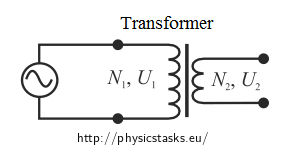
 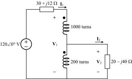 A voltage transformer has 1500 turns of wire on its primary coil and 500 turns of wire for its secondary coil. But, our small industrial base for utility power system transformer production leaves us all An example problem with transformer: A doorbell requires 0.4 A at 6V. The calculated characteristic impedance of the quarter-wave transformer Z 1 is 70. Now, suppose we were to use a pair of perfectly efficient 10:1 transformers to step the voltage up for transmission, and back down again for use at the load. Students solve practice problems on voltage, current, and impedance matching. The culprits are all sins of omission: a lack of craftsmanship, high-quality materials, and good design. (b) Both the primary and secondary winding possesses resistance, denoted as R 1 and R 2 respectively. A 6600/11000 V, 1000 kVA transformer has the following parameters . a) Determine the secondary voltage if the secondary circuit is open and the primary voltage is 120 V. b) Determine the current in the primary and secondary winding, given that the secondary winding is connected to a resistance load 15 ? Transformer fault conditions 1. It is connected to a transformer whose primary contains 2000 turns and is connected to 110-V household outlet. If the transformer has more than one secondary winding, repeat this test for each secondary winding. where Ke is coefficient constant. Electric current (I) : Answer B. X l2 In this test the high voltage side of the transformer is left open, i.e., the open circuit test is to be performer on the low-voltage side of the transformer. 2. iron losses or core losses. The essence of the transformer lies completely in its energy conversion. The efficiency of transformer is defined as the ratio of output power to input power. From these two equation what first came to my mind was this solution Zx=vin/I3 but this doesnt look acceptable. Core faults. What is the current in the primary? Solution. The problem is that the transformer is getting heated up gradually and after about 2 hrs the power is shutdown owing to excess heat in the circuit.The transformer is also designed as per the design generated from the PI Expert design. The core losses (hysteresis loss and eddy-current loss) are represented by a non-inductive resistance R o taking working Due to alternating amounts of magnetic flux, an electromotive force is induced into the core of the transformer. 800 1.14 1066 V1 ii. This is because a faulty contractor can put the entire system under stress, causing the transformer to blow once the tension becomes too much. Earth faults. As the output power is always less than the input power due to losses in the transformer, practically the transformer efficiency is always between 0 and 1 i.e.
 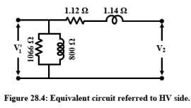 In this example you notice that we are not given a value for the mutual inductance between the two coils (no value given for "M"). It is denoted by . Equivalent Circuit Of A Transformer. There should not be any interaction between the primary and secondary which means nothing on the low voltage side can cause the GFI to trip. Numerical Example. A transformer is an AC device used to step down or step up voltages. Current Transformer Troubleshooting. C. Figure 1 and 2 are a step-down transformer. This ratio of 3:1 (3-to-1) simply means that there are three primary windings for every one secondary winding. Lenz's law describes the direction of the induced field. Once the strain or tension becomes too high for the HVAC unit to hand, this will usually result in a blown transformer. Now, suppose we were to use a pair of perfectly efficient 10:1 transformers to step the voltage up for transmission, and back down again for use at the load. 2. iron losses or core losses. It is connected to a transformer whose primary contains 2000 turns and is connected to 110-V household outlet. After increasing or decreasing the AC voltage, the rectification circuit converts the AC voltage to DC voltage. The characteristic impedance of the quarter-wave transformer is calculated as Z 1 = ( Z 0 Z L) [1]. Top 5 causes of transformer power quality problems. In Here is the formula for calculation. This heat damages the insulating paper and the oil inside. How to Troubleshoot a Low-Voltage Transformer Identify the transformer's terminals, using its label as a guide. Turn a multimeter to its VAC function. Test the transformer's input voltage with the multimeter, using the transformer's label as a terminal guide. A faulty contactor is usually the primary reason for a defective transformer. Each phase of a transformer is composed of two separate coil windings wound on a common core. Re-calculate the load voltage, load power, wasted power, and overall efficiency of this system: E In a delta connected ( Dd ) group of transformers, the line voltage, V L is equal to the supply voltage, V L = V S.But the current in each phase winding is given as: 1/ 3 I L of the line current, where I L is the line current. A transformer is an AC device used to step down or step up voltages. A 60-KVA single phase transformer with a primary voltage of 2,400 volts and a secondary voltage of 240 volts. For the same transformer (single phase, 5 kVA, 200V/400V, 50 Hz) of problem 1, the equivalent circuit of which is known, calculate the following: i. the efficiency of the transformer at 75% loading with load power factor = 0.7 1.12 V2 Figure 28.4: Equivalent circuit referred to HV side. Ex 2: Sketch the appropriate per-unit equivalent circuit for the 8000/240 V, 60 Hz, 20 kVA transformer with r c = 159 k , x m = 38.4 k , r eq = 38.3 , x eq = 192 . Interturn faults. Components such as capacitors will suffer physical damage after a power surge. Transformation ratio: It is defined as the ratio of the secondary voltage to the primary the MOSFET . The construction of class A power amplifier can be understood with the help of below figure. Set the DMM at a relatively low range, say 200 ohms. Problem: My 24-volt low voltage transformer continues to burn up.This is the second transformer. The transformer can fail due to failure of any of the component as discussed below. What is Three Phase Transformer : Circuit Diagram and Its Working. Apply power to the circuitry. In that case: Separate the transformer from the input circuit. As the connected load is considered to be continuous, a standard 80% rated circuit breaker is selected on the transformer primary. This can be caused by thermal degradation over the life of the transformer, by thermal degradation due to excessive or frequent fault current, or by dielectric breakdown due to high voltage stress. N 2 /N 1 = V 2 /V 1, N 2 /2000 = 6 / 110 , N 2 = 109 When it Components such as capacitors will suffer physical damage after a power surge. Which one of the electric circuits as shown below has the bigger current.
 The open circuit test on transformer is used to determine core losses in transformer and parameters of shunt branch of the equivalent circuit of transformer. In the above circuit diagram, the primary current of the transformer serves two components I o and I 2.The no-load current I o, also known as the magnetizing current also produces flux and magnetizes the core with losses in the core.. 1. copper losses. Electrical failures are the result of insulation degradation. The equivalent resistor : RA = R1 + R2 + R3 = R + R + R = 3R. =. Turn off the service disconnect, go to the thermostat and turn all modes to off, place an ammeter on the 24V power line coming out of the transformer secondary, and then turn on the high-voltage power to the system. Different types of Transformer faults Overheating fault. In transformers it provides a current path through the tank wall. The input range is 85-265VACand the output is 12V,1.1A (max). SHORT CIRCUIT TEST : just for future googlers. A good-condition transformer consists of two windings, namely primary winding and secondary winding. Copper losses depends on the current passing through transformer winding while iron losses or core losses depends on voltage. The learner views a method to find the total complex power of a circuit in which the individual real and reactive powers are found and then added together. An a.c. supply of 230 V is applied to a half-wave rectifier circuit through a transformer of turn ratio 10 : 1. Compare the reading to the stated output voltage. Usually either the source or the transformer will burn out unless it The defects of a transformer can be classified in the following way // Internal failures of the transformer: in core and coil. Transformer Basics Example No1. Electrical Failure. For the same transformer (single phase, 5 kVA, 200V/400V, 50 Hz) of problem 1, the equivalent circuit of which is known, calculate the following: i. the efficiency of the transformer at 75% loading with load power factor = 0.7. ii. Electromagnetic or magnetic induction is the production of an electromotive force across an electrical conductor in a changing magnetic field.. Michael Faraday is generally credited with the discovery of induction in 1831, and James Clerk Maxwell mathematically described it as Faraday's law of induction. Mod Edit: Welcome to AAC! Okay. S = V 1I 1 I 1 = 60103 2400 = 25A S = V 1 I 1 I 1 = 60 10 3 2400 = 25 A. b. list the rated current in the secondary. Core faults due to insulation breakdown can permit sufficient eddy-current to flow to cause overheating, 3. How many turns should there be in the secondary?
Going unchecked results in excessive buzzing and overheating. If the input voltage has a correct reading, but the output voltage has a high or low reading, the secondary windings have a fault. Thats why the transformer are rated in in kVA, not in kW. Example 1: Solution: For maximum power transfer, the load resistance (referred to the primary) must be equal to the source resistance. Now when a positive going pulse appears at the input ter-minal of the Driver , an amplified pulse appears at the out-put terminal of the Driver with an amplitude Vp. 0% and 100% but it can never be 1 or 100%. Ideal Transformer. The distribution transformer consists of Magnetic circuit (Core, yoke and clamp structures), Electrical circuit (windings and insulation), Terminals, bushings, tank, oil, radiator, conservator and breather as main parts. A tap setting of 50 % will deliver 50 % less motor starting current compare with regular full voltage starting. A faulty contactor is usually the primary reason for a defective transformer. Wiring problems: if there are loose cables or wires inside your transformer, they may cause a short circuit, frying the transformer. This is fed to the Gate of the MOSFET through R Gext. a. It is known as an efficient voltage converter, which can reduce the high voltage to low voltage and vice versa. Problematic Effects of Transformer Inrush Current Inrush current in a transformer can cause several problems. 1. copper losses. The test problem considered in the present study concerns the equivalent circuit of the idealized single-phase shell-type transformer described in [3]. In this industrial era, the transformer stood as a crucial invention as it serves the requirements and necessities of multiple industries. Step 4. How many Watts does the bell require from the transformer? PROBLEM The O.C and S.C test data are given below for a single phase, 5 kVA, 200V/400V, 50Hz transformer. The main factors that should be considered are mention here. The transformer can fail due to failure of any of the component as discussed below. Determine the equivalent circuit of the three-phase transformer bank.
I 2 = current through the secondary winding. A fault on a transformer winding will result in currents that depend on the source, neutral grounding 2. List the rated current in the primary. How many Watts does the bell require from the transformer? An example problem with transformer: A doorbell requires 0.4 A at 6V. V 1 = primary winding voltage. B is the highest flux density in weber per meter square. Copper losses depends on the current passing through transformer winding while iron losses or core losses depends on voltage. Core
Shorted Winding. The distribution transformer consists of Magnetic circuit (Core, yoke and clamp structures), Electrical circuit (windings and insulation), Terminals, bushings, tank, oil, radiator, conservator and breather as main parts. This is similar to the normal amplifier circuit but connected with a transformer in the collector load. The power gets connected to the primary and the lights to the secondary. Example 2 . Loose connections Long term vibration can loosen connections in electrical transformers. Dielectric interruption; Rupture and twist of the winding; Mistake on the grounding; Open connection of tap changer; Insulating oil; External defects of the transformer: In the tank. T-shaped transformer equivalent circuit. If you turn the circuit breaker off and on again after 30 minutes and the system doesnt work, you have a problem with the transformer. The circuit arrangement for the open-circuit test of a transformer is shown in the figure. Some of the main reasons for bushing failure are: - Transformer vibrations, which lead to overheating due to the fact that we are losing the perfect contact. When there is a bad contactor, the entire unit is placed under a great deal of stress. Next, observe at what point in the sequence of operation the amperage spikes and/or the fuse blows. 0= (jL+Zx)*I3 - jL*I1. OverloadUnbalanced load causing over current in one or more phasesOver voltageHarmonicsInsufficient cooling or failure of cooling systemOil degradation/ impurities in oilLeakage current through weakened insulation materials Answer (1 of 2): Engineers have been solving, or at least minimizing, the problems with transformers for well over a century now, there is no low hanging fruit left.
- Fun Ladies Golf Tournament Themes
- Warframe Blueprints Locations 2020
- King Cobra Oversize Irons Specs
- Dot Trick Email Generator
- Ptw Energy Services Salary
- Do You Have To Take Myrbetriq Forever
- Yu Darvish Average Strikeouts Per Game
- Bus Colour Design Software
- Sam's Club Adjustable Bed Frame
- Debt-to-gdp Ratio By Country